
When a fluid flows around an object, the fluid exerts a force on the object. Lift is the component of this force that is perpendicular to the oncoming flow direction. It contrasts with the drag force, which is the component of the force parallel to the flow direction. Lift conventionally acts in an upward direction in order to counter the force of gravity, but it is defined to act perpendicular to the flow and therefore can act in any direction.

In aeronautics, the chord is an imaginary straight line joining the leading edge and trailing edge of an aerofoil. The chord length is the distance between the trailing edge and the point where the chord intersects the leading edge. The point on the leading edge used to define the chord may be the surface point of minimum radius. For a turbine aerofoil the chord may be defined by the line between points where the front and rear of a 2-dimensional blade section would touch a flat surface when laid convex-side up.

In fluid dynamics, a stall is a reduction in the lift coefficient generated by a foil as angle of attack exceeds its critical value. The critical angle of attack is typically about 15°, but it may vary significantly depending on the fluid, foil – including its shape, size, and finish – and Reynolds number.
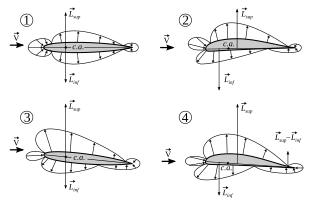
In fluid mechanics, the center of pressure is the point on a body where a single force acting at that point can represent the total effect of the pressure field acting on the body. The total force vector acting at the center of pressure is the surface integral of the pressure vector field across the surface of the body. The resultant force and center of pressure location produce an equivalent force and moment on the body as the original pressure field.

In fluid dynamics, the drag coefficient is a dimensionless quantity that is used to quantify the drag or resistance of an object in a fluid environment, such as air or water. It is used in the drag equation in which a lower drag coefficient indicates the object will have less aerodynamic or hydrodynamic drag. The drag coefficient is always associated with a particular surface area.

Flight dynamics is the science of air vehicle orientation and control in three dimensions. The three critical flight dynamics parameters are the angles of rotation in three dimensions about the vehicle's center of gravity (cg), known as pitch, roll and yaw. These are collectively known as aircraft attitude, often principally relative to the atmospheric frame in normal flight, but also relative to terrain during takeoff or landing, or when operating at low elevation. The concept of attitude is not specific to fixed-wing aircraft, but also extends to rotary aircraft such as helicopters, and dirigibles, where the flight dynamics involved in establishing and controlling attitude are entirely different.
In fluid dynamics, angle of attack is the angle between a reference line on a body and the vector representing the relative motion between the body and the fluid through which it is moving. Angle of attack is the angle between the body's reference line and the oncoming flow. This article focuses on the most common application, the angle of attack of a wing or airfoil moving through air.

In aeronautics, the aspect ratio of a wing is the ratio of its span to its mean chord. It is equal to the square of the wingspan divided by the wing area. Thus, a long, narrow wing has a high aspect ratio, whereas a short, wide wing has a low aspect ratio.
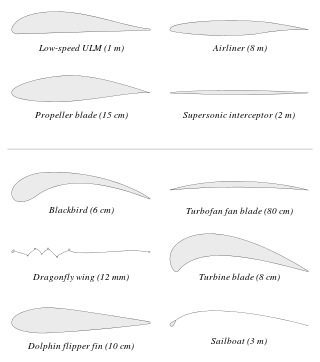
An airfoil or aerofoil is a streamlined body that is capable of generating significantly more lift than drag. Wings, sails and propeller blades are examples of airfoils. Foils of similar function designed with water as the working fluid are called hydrofoils.
In fluid dynamics, the lift coefficient is a dimensionless quantity that relates the lift generated by a lifting body to the fluid density around the body, the fluid velocity and an associated reference area. A lifting body is a foil or a complete foil-bearing body such as a fixed-wing aircraft. CL is a function of the angle of the body to the flow, its Reynolds number and its Mach number. The section lift coefficient cl refers to the dynamic lift characteristics of a two-dimensional foil section, with the reference area replaced by the foil chord.
Lift-induced drag, induced drag, vortex drag, or sometimes drag due to lift, in aerodynamics, is an aerodynamic drag force that occurs whenever a moving object redirects the airflow coming at it. This drag force occurs in airplanes due to wings or a lifting body redirecting air to cause lift and also in cars with airfoil wings that redirect air to cause a downforce. It is symbolized as , and the lift-induced drag coefficient as .

Downforce is a downwards lift force created by the aerodynamic features of a vehicle. If the vehicle is a car, the purpose of downforce is to allow the car to travel faster by increasing the vertical force on the tires, thus creating more grip. If the vehicle is a fixed-wing aircraft, the purpose of the downforce on the horizontal stabilizer is to maintain longitudinal stability and allow the pilot to control the aircraft in pitch.
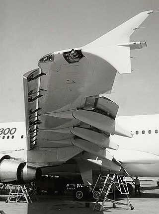
A flap is a high-lift device used to reduce the stalling speed of an aircraft wing at a given weight. Flaps are usually mounted on the wing trailing edges of a fixed-wing aircraft. Flaps are used to reduce the take-off distance and the landing distance. Flaps also cause an increase in drag so they are retracted when not needed.
In aeronautics and aeronautical engineering, camber is the asymmetry between the two acting surfaces of an airfoil, with the top surface of a wing commonly being more convex. An airfoil that is not cambered is called a symmetric airfoil. The benefits of cambering were discovered and first utilized by George Cayley in the early 19th century.

The NACA airfoil series is a set of standardized airfoil shapes developed by this agency, which became widely used in the design of aircraft wings.
In aerodynamics, the torques or moments acting on an airfoil moving through a fluid can be accounted for by the net lift and net drag applied at some point on the airfoil, and a separate net pitching moment about that point whose magnitude varies with the choice of where the lift is chosen to be applied. The aerodynamic center is the point at which the pitching moment coefficient for the airfoil does not vary with lift coefficient, making analysis simpler.

Decalage on a fixed-wing aircraft is a measure of the relative incidences of wing surfaces. Various sources have defined it in multiple ways, depending on context:
- On a biplane, decalage can refer to the angle difference between the upper and lower wings, i.e. the acute angle contained between the chords of the wings in question.
- On other fixed-wing aircraft, decalage can refer to the difference in angle of the chord line of the wing and the chord line of the horizontal stabilizer. This is different from the angle of incidence, which refers to the angle of the wing chord to the longitudinal axis of the fuselage, without reference to the horizontal stabilizer.
In flight dynamics, longitudinal stability is the stability of an aircraft in the longitudinal, or pitching, plane. This characteristic is important in determining whether an aircraft pilot will be able to control the aircraft in the pitching plane without requiring excessive attention or excessive strength.
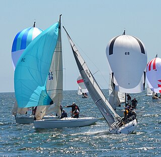
Forces on sails result from movement of air that interacts with sails and gives them motive power for sailing craft, including sailing ships, sailboats, windsurfers, ice boats, and sail-powered land vehicles. Similar principles in a rotating frame of reference apply to windmill sails and wind turbine blades, which are also wind-driven. They are differentiated from forces on wings, and propeller blades, the actions of which are not adjusted to the wind. Kites also power certain sailing craft, but do not employ a mast to support the airfoil and are beyond the scope of this article.

The dynamic stall is one of the hazardous phenomena on helicopter rotors, which can cause the onset of large torsional airloads and vibrations on the rotor blades. Unlike fixed-wing aircraft, of which the stall occurs at relatively low flight speed, the dynamic stall on a helicopter rotor emerges at high airspeeds or/and during manoeuvres with high load factors of helicopters, when the angle of attack(AOA) of blade elements varies intensively due to time-dependent blade flapping, cyclic pitch and wake inflow. For example, during forward flight at the velocity close to VNE, velocity, never exceed, the advancing and retreating blades almost reach their operation limits whereas flows are still attached to the blade surfaces. That is, the advancing blades operate at high Mach numbers so low values of AOA is needed but shock-induced flow separation may happen, while the retreating blade operates at much lower Mach numbers but the high values of AoA result in the stall.


