Center of pressure (fluid mechanics)

Last updated

In fluid mechanics, the center of pressure is the point where the total sum of a pressure field acts on a body, causing a force to act through that point. The total force vector acting at the center of pressure is the surface integral of the pressure vector field across the surface of the body. The resultant force and center of pressure location produce an equivalent force and moment on the body as the original pressure field.

Contents

Pressure fields occur in both static and dynamic fluid mechanics. Specification of the center of pressure, the reference point from which the center of pressure is referenced, and the associated force vector allows the moment generated about any point to be computed by a translation from the reference point to the desired new point. It is common for the center of pressure to be located on the body, but in fluid flows it is possible for the pressure field to exert a moment on the body of such magnitude that the center of pressure is located outside the body. [1]

Hydrostatic example (dam)

Since the forces of water on a dam are hydrostatic forces, they vary linearly with depth. The total force on the dam is then the integral of the pressure multiplied by the width of the dam as a function of the depth. The center of pressure is located at the centroid of the triangular shaped pressure field from the top of the water line. The hydrostatic force and tipping moment on the dam about some point can be computed from the total force and center of pressure location relative to the point of interest.

Historical usage for sailboats

Center of pressure is used in sailboat design to represent the position on a sail where the aerodynamic force is concentrated.

The relationship of the aerodynamic center of pressure on the sails to the hydrodynamic center of pressure (referred to as the center of lateral resistance) on the hull determines the behavior of the boat in the wind. This behavior is known as the "helm" and is either a weather helm or lee helm. A slight amount of weather helm is thought by some sailors to be a desirable situation, both from the standpoint of the "feel" of the helm, and the tendency of the boat to head slightly to windward in stronger gusts, to some extent self-feathering the sails. Other sailors disagree and prefer a neutral helm.

The fundamental cause of "helm", be it weather or lee, is the relationship of the center of pressure of the sail plan to the center of lateral resistance of the hull. If the center of pressure is astern of the center of lateral resistance, a weather helm, the tendency of the vessel is to want to turn into the wind.

If the situation is reversed, with the center of pressure forward of the center of lateral resistance of the hull, a "lee" helm will result, which is generally considered undesirable, if not dangerous. Too much of either helm is not good, since it forces the helmsman to hold the rudder deflected to counter it, thus inducing extra drag beyond what a vessel with neutral or minimal helm would experience. [2]

Aircraft aerodynamics

A stable configuration is desirable not only in sailing, but in aircraft design as well. Aircraft design therefore borrowed the term center of pressure. And like a sail, a rigid non-symmetrical airfoil not only produces lift, but a moment. The center of pressure of an aircraft is the point where all of the aerodynamic pressure field may be represented by a single force vector with no moment. [3] [4] A similar idea is the aerodynamic center which is the point on an airfoil where the pitching moment produced by the aerodynamic forces is constant with angle of attack. [5] [6] [7]

The aerodynamic center plays an important role in analysis of the longitudinal static stability of all flying machines. It is desirable that when the pitch angle and angle of attack of an aircraft are disturbed (by, for example wind shear/vertical gust) that the aircraft returns to its original trimmed pitch angle and angle of attack without a pilot or autopilot changing the control surface deflection. For an aircraft to return towards its trimmed attitude, without input from a pilot or autopilot, it must have positive longitudinal static stability. [8]

Missile aerodynamics

Missiles typically do not have a preferred plane or direction of maneuver and thus have symmetric airfoils. Since the center of pressure for symmetric airfoils is relatively constant for small angle of attack, missile engineers typically speak of the complete center of pressure of the entire vehicle for stability and control analysis. In missile analysis, the center of pressure is typically defined as the center of the additional pressure field due to a change in the angle of attack off of the trim angle of attack. [9]

For unguided rockets the trim position is typically zero angle of attack and the center of pressure is defined to be the center of pressure of the resultant flow field on the entire vehicle resulting from a very small angle of attack (that is, the center of pressure is the limit as angle of attack goes to zero). For positive stability in missiles, the total vehicle center of pressure defined as given above must be further from the nose of the vehicle than the center of gravity. In missiles at lower angles of attack, the contributions to the center of pressure are dominated by the nose, wings, and fins. The normalized normal force coefficient derivative with respect to the angle of attack of each component multiplied by the location of the center of pressure can be used to compute a centroid representing the total center of pressure. The center of pressure of the added flow field is behind the center of gravity and the additional force "points" in the direction of the added angle of attack; this produces a moment that pushes the vehicle back to the trim position.

In guided missiles where the fins can be moved to trim the vehicles in different angles of attack, the center of pressure is the center of pressure of the flow field at that angle of attack for the undeflected fin position. This is the center of pressure of any small change in the angle of attack (as defined above). Once again for positive static stability, this definition of center of pressure requires that the center of pressure be further from the nose than the center of gravity. This ensures that any increased forces resulting from increased angle of attack results in increased restoring moment to drive the missile back to the trimmed position. In missile analysis, positive static margin implies that the complete vehicle makes a restoring moment for any angle of attack from the trim position.

Movement of center of pressure for aerodynamic fields

The center of pressure on a symmetric airfoil typically lies close to 25% of the chord length behind the leading edge of the airfoil. (This is called the "quarter-chord point".) For a symmetric airfoil, as angle of attack and lift coefficient change, the center of pressure does not move. [10] It remains around the quarter-chord point for angles of attack below the stalling angle of attack. The role of center of pressure in the control characterization of aircraft takes a different form than in missiles.

On a cambered airfoil the center of pressure does not occupy a fixed location. [11] For a conventionally cambered airfoil, the center of pressure lies a little behind the quarter-chord point at maximum lift coefficient (large angle of attack), but as lift coefficient reduces (angle of attack reduces) the center of pressure moves toward the rear. [12] When the lift coefficient is zero an airfoil is generating no lift but a conventionally cambered airfoil generates a nose-down pitching moment, so the location of the center of pressure is an infinite distance behind the airfoil.

For a reflex-cambered airfoil, the center of pressure lies a little ahead of the quarter-chord point at maximum lift coefficient (large angle of attack), but as lift coefficient reduces (angle of attack reduces) the center of pressure moves forward. When the lift coefficient is zero an airfoil is generating no lift but a reflex-cambered airfoil generates a nose-up pitching moment, so the location of the center of pressure is an infinite distance ahead of the airfoil. This direction of movement of the center of pressure on a reflex-cambered airfoil has a stabilising effect.

The way the center of pressure moves as lift coefficient changes makes it difficult to use the center of pressure in the mathematical analysis of longitudinal static stability of an aircraft. For this reason, it is much simpler to use the aerodynamic center when carrying out a mathematical analysis. The aerodynamic center occupies a fixed location on an airfoil, typically close to the quarter-chord point.

The aerodynamic center is the conceptual starting point for longitudinal stability. The horizontal stabilizer contributes extra stability and this allows the center of gravity to be a small distance aft of the aerodynamic center without the aircraft reaching neutral stability. The position of the center of gravity at which the aircraft has neutral stability is called the neutral point.

See also

Notes

  1. Flightwise Volume 2 Aircraft Stability and Control, Christopher Carpenter 1997, ISBN   1 85310 870 7, p.75
  2. Marchaj, C.A. (1985). Sailing Theory and Practice, Revised edition. Putnam. ISBN   978-0-396-08428-0
  3. Clancy, L.J., Aerodynamics, Section 5.3
  4. Anderson, John D., Aircraft Performance and Design, Section 2.3
  5. Preston, Ray (2006). "Aerodynamic Center". Aerodynamics Text. Selkirk College. Archived from the original on 2006-02-21. Retrieved 2006-04-01.
  6. Clancy, L.J., Aerodynamics, Section 5.10
  7. Anderson, John D., Aircraft Performance and Design, Section 2.5
  8. Clancy, L.J., Aerodynamics, Sections 16.1 and 16.2
  9. Moore, F.G., Approximate Methods for Weapon Aerodynamics, AIAA Progress in Astronatuics and Aeronautics, Volume 186
  10. Anderson, John D. Jr (1984) Fundamentals of Aerodynamics, Section 4.7, (p.211), McGraw-Hill. ISBN 0-07-001656-9
  11. Clancy, L.J., Aerodynamics, Section 5.6
  12. Clancy, L.J., Aerodynamics, Section 5.11

Related Research Articles

<span class="mw-page-title-main">Lift (force)</span> Force perpendicular to flow of surrounding fluid

When a fluid flows around an object, the fluid exerts a force on the object. Lift is the component of this force that is perpendicular to the oncoming flow direction. It contrasts with the drag force, which is the component of the force parallel to the flow direction. Lift conventionally acts in an upward direction in order to counter the force of gravity, but it is defined to act perpendicular to the flow and therefore can act in any direction.

<span class="mw-page-title-main">Stall (fluid dynamics)</span> Abrupt reduction in lift due to flow separation

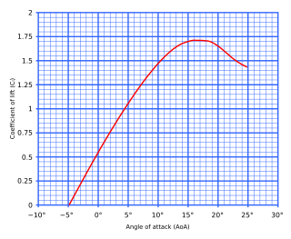
In fluid dynamics, a stall is a reduction in the lift coefficient generated by a foil as angle of attack increases. This occurs when the critical angle of attack of the foil is exceeded. The critical angle of attack is typically about 15°, but it may vary significantly depending on the fluid, foil, and Reynolds number.

<span class="mw-page-title-main">Aircraft flight dynamics</span> Science of air vehicle orientation and control in three dimensions

Flight dynamics is the science of air vehicle orientation and control in three dimensions. The three critical flight dynamics parameters are the angles of rotation in three dimensions about the vehicle's center of gravity (cg), known as pitch, roll and yaw. These are collectively known as aircraft attitude, often principally relative to the atmospheric frame in normal flight, but also relative to terrain during takeoff or landing, or when operating at low elevation. The concept of attitude is not specific to fixed-wing aircraft, but also extends to rotary aircraft such as helicopters, and dirigibles, where the flight dynamics involved in establishing and controlling attitude are entirely different.

In fluid dynamics, angle of attack is the angle between a reference line on a body and the vector representing the relative motion between the body and the fluid through which it is moving. Angle of attack is the angle between the body's reference line and the oncoming flow. This article focuses on the most common application, the angle of attack of a wing or airfoil moving through air.

<span class="mw-page-title-main">Aspect ratio (aeronautics)</span> Ratio of an aircrafts wing span to its mean chord

In aeronautics, the aspect ratio of a wing is the ratio of its span to its mean chord. It is equal to the square of the wingspan divided by the wing area. Thus, a long, narrow wing has a high aspect ratio, whereas a short, wide wing has a low aspect ratio.

<span class="mw-page-title-main">Airfoil</span> Cross-sectional shape of a wing, blade of a propeller, rotor, or turbine, or sail

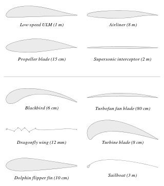
An airfoil or aerofoil is a streamlined body that is capable of generating significantly more lift than drag. Wings, sails and propeller blades are examples of airfoils. Foils of similar function designed with water as the working fluid are called hydrofoils.

In fluid dynamics, the lift coefficient is a dimensionless quantity that relates the lift generated by a lifting body to the fluid density around the body, the fluid velocity and an associated reference area. A lifting body is a foil or a complete foil-bearing body such as a fixed-wing aircraft. CL is a function of the angle of the body to the flow, its Reynolds number and its Mach number. The section lift coefficient cl refers to the dynamic lift characteristics of a two-dimensional foil section, with the reference area replaced by the foil chord.

<span class="mw-page-title-main">Flap (aeronautics)</span> Anti-stalling high-lift device on aircraft

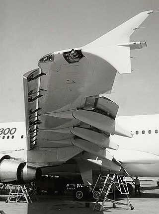
A flap is a high-lift device used to reduce the stalling speed of an aircraft wing at a given weight. Flaps are usually mounted on the wing trailing edges of a fixed-wing aircraft. Flaps are used to reduce the take-off distance and the landing distance. Flaps also cause an increase in drag so they are retracted when not needed.

Aircraft flight mechanics are relevant to fixed wing and rotary wing (helicopters) aircraft. An aeroplane, is defined in ICAO Document 9110 as, "a power-driven heavier than air aircraft, deriving its lift chiefly from aerodynamic reactions on surface which remain fixed under given conditions of flight".

The United States Air Force Stability and Control Digital DATCOM is a computer program that implements the methods contained in the USAF Stability and Control DATCOM to calculate the static stability, control and dynamic derivative characteristics of fixed-wing aircraft. Digital DATCOM requires an input file containing a geometric description of an aircraft, and outputs its corresponding dimensionless stability derivatives according to the specified flight conditions. The values obtained can be used to calculate meaningful aspects of flight dynamics.

<span class="mw-page-title-main">Stabilizer (aeronautics)</span> Aircraft component

An aircraft stabilizer is an aerodynamic surface, typically including one or more movable control surfaces, that provides longitudinal (pitch) and/or directional (yaw) stability and control. A stabilizer can feature a fixed or adjustable structure on which any movable control surfaces are hinged, or it can itself be a fully movable surface such as a stabilator. Depending on the context, "stabilizer" may sometimes describe only the front part of the overall surface.

In aeronautics and aeronautical engineering, camber is the asymmetry between the two acting surfaces of an airfoil, with the top surface of a wing commonly being more convex. An airfoil that is not cambered is called a symmetric airfoil. The benefits of cambering were discovered and first utilized by George Cayley in the early 19th century.

<span class="mw-page-title-main">NACA airfoil</span> Wing shape

NACA stands for the National Advisory Committee for Aeronautics, which was a U.S. federal agency founded in 1915 to undertake, promote, and institutionalize aeronautical research. It played a crucial role in advancing aviation technology, including the development of airfoils, which are the cross-sectional shapes of wings and other aerodynamic surfaces. The NACA airfoil series is a set of standardized airfoil shapes developed by this agency, which became widely used in the design of aircraft wings.

<span class="mw-page-title-main">Aerodynamic center</span> Point on an airfoil where pitching moment coefficient is constant for all angles of attack

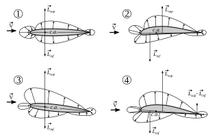
In aerodynamics, the torques or moments acting on an airfoil moving through a fluid can be accounted for by the net lift and net drag applied at some point on the airfoil, and a separate net pitching moment about that point whose magnitude varies with the choice of where the lift is chosen to be applied. The aerodynamic center is the point at which the pitching moment coefficient for the airfoil does not vary with lift coefficient, making analysis simpler.

<span class="mw-page-title-main">Pitching moment</span> Torque on an airfoil from forces applied at the aerodynamic center

In aerodynamics, the pitching moment on an airfoil is the moment produced by the aerodynamic force on the airfoil if that aerodynamic force is considered to be applied, not at the center of pressure, but at the aerodynamic center of the airfoil. The pitching moment on the wing of an airplane is part of the total moment that must be balanced using the lift on the horizontal stabilizer. More generally, a pitching moment is any moment acting on the pitch axis of a moving body.

<span class="mw-page-title-main">Zero-lift axis</span>

A cambered aerofoil generates no lift when it is moving parallel to an axis called the zero-lift axis When the angle of attack on an aerofoil is measured relative to the zero-lift axis it is true to say the lift coefficient is zero when the angle of attack is zero. For this reason, on a cambered aerofoil the zero-lift line is better than the chord line when describing the angle of attack.

<span class="mw-page-title-main">Canard (aeronautics)</span> Aircraft configuration in which a small wing is placed in front of the main wing

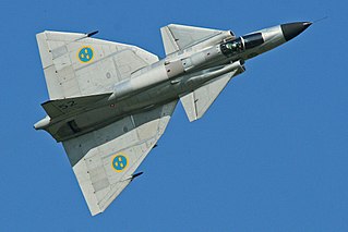
In aeronautics, a canard is a wing configuration in which a small forewing or foreplane is placed forward of the main wing of a fixed-wing aircraft or a weapon. The term "canard" may be used to describe the aircraft itself, the wing configuration, or the foreplane. Canard wings are also extensively used in guided missiles and smart bombs.

In flight dynamics, longitudinal stability is the stability of an aircraft in the longitudinal, or pitching, plane. This characteristic is important in determining whether an aircraft pilot will be able to control the aircraft in the pitching plane without requiring excessive attention or excessive strength.

<span class="mw-page-title-main">Forces on sails</span>

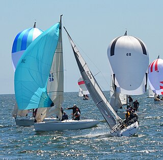
Forces on sails result from movement of air that interacts with sails and gives them motive power for sailing craft, including sailing ships, sailboats, windsurfers, ice boats, and sail-powered land vehicles. Similar principles in a rotating frame of reference apply to windmill sails and wind turbine blades, which are also wind-driven. They are differentiated from forces on wings, and propeller blades, the actions of which are not adjusted to the wind. Kites also power certain sailing craft, but do not employ a mast to support the airfoil and are beyond the scope of this article.

<span class="mw-page-title-main">Dynamic stall on helicopter rotors</span> Dynamic stall on helicopter rotors

The dynamic stall is one of the hazardous phenomena on helicopter rotors, which can cause the onset of large torsional airloads and vibrations on the rotor blades. Unlike fixed-wing aircraft, of which the stall occurs at relatively low flight speed, the dynamic stall on a helicopter rotor emerges at high airspeeds or/and during manoeuvres with high load factors of helicopters, when the angle of attack(AOA) of blade elements varies intensively due to time-dependent blade flapping, cyclic pitch and wake inflow. For example, during forward flight at the velocity close to VNE, velocity, never exceed, the advancing and retreating blades almost reach their operation limits whereas flows are still attached to the blade surfaces. That is, the advancing blades operate at high Mach numbers so low values of AOA is needed but shock-induced flow separation may happen, while the retreating blade operates at much lower Mach numbers but the high values of AoA result in the stall.

References