
When a fluid flows around an object, the fluid exerts a force on the object. Lift is the component of this force that is perpendicular to the oncoming flow direction. It contrasts with the drag force, which is the component of the force parallel to the flow direction. Lift conventionally acts in an upward direction in order to counter the force of gravity, but it is defined to act perpendicular to the flow and therefore can act in any direction.

A wing is a type of fin that produces lift while moving through air or some other fluid. Accordingly, wings have streamlined cross-sections that are subject to aerodynamic forces and act as airfoils. A wing's aerodynamic efficiency is expressed as its lift-to-drag ratio. The lift a wing generates at a given speed and angle of attack can be one to two orders of magnitude greater than the total drag on the wing. A high lift-to-drag ratio requires a significantly smaller thrust to propel the wings through the air at sufficient lift.

In aeronautics, the chord is an imaginary straight line joining the leading edge and trailing edge of an aerofoil. The chord length is the distance between the trailing edge and the point where the chord intersects the leading edge. The point on the leading edge used to define the chord may be the surface point of minimum radius. For a turbine aerofoil the chord may be defined by the line between points where the front and rear of a 2-dimensional blade section would touch a flat surface when laid convex-side up.

An aileron is a hinged flight control surface usually forming part of the trailing edge of each wing of a fixed-wing aircraft. Ailerons are used in pairs to control the aircraft in roll, which normally results in a change in flight path due to the tilting of the lift vector. Movement around this axis is called 'rolling' or 'banking'.

Aeroelasticity is the branch of physics and engineering studying the interactions between the inertial, elastic, and aerodynamic forces occurring while an elastic body is exposed to a fluid flow. The study of aeroelasticity may be broadly classified into two fields: static aeroelasticity dealing with the static or steady state response of an elastic body to a fluid flow, and dynamic aeroelasticity dealing with the body's dynamic response.

In fluid dynamics, a stall is a reduction in the lift coefficient generated by a foil as angle of attack exceeds its critical value. The critical angle of attack is typically about 15°, but it may vary significantly depending on the fluid, foil – including its shape, size, and finish – and Reynolds number.

A delta wing is a wing shaped in the form of a triangle. It is named for its similarity in shape to the Greek uppercase letter delta (Δ).
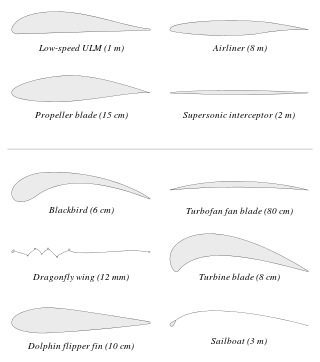
An airfoil or aerofoil is a streamlined body that is capable of generating significantly more lift than drag. Wings, sails and propeller blades are examples of airfoils. Foils of similar function designed with water as the working fluid are called hydrofoils.
Lift-induced drag, induced drag, vortex drag, or sometimes drag due to lift, in aerodynamics, is an aerodynamic drag force that occurs whenever a moving object redirects the airflow coming at it. This drag force occurs in airplanes due to wings or a lifting body redirecting air to cause lift and also in cars with airfoil wings that redirect air to cause a downforce. It is symbolized as , and the lift-induced drag coefficient as .

Aircraft flight control surfaces are aerodynamic devices allowing a pilot to adjust and control the aircraft's flight attitude.

In aircraft design and aerospace engineering, a high-lift device is a component or mechanism on an aircraft's wing that increases the amount of lift produced by the wing. The device may be a fixed component, or a movable mechanism which is deployed when required. Common movable high-lift devices include wing flaps and slats. Fixed devices include leading-edge slots, leading edge root extensions, and boundary layer control systems.
A flap is a high-lift device used to reduce the stalling speed of an aircraft wing at a given weight. Flaps are usually mounted on the wing trailing edges of a fixed-wing aircraft. Flaps are used to reduce the take-off distance and the landing distance. Flaps also cause an increase in drag so they are retracted when not needed.

The empennage, also known as the tail or tail assembly, is a structure at the rear of an aircraft that provides stability during flight, in a way similar to the feathers on an arrow. The term derives from the French language verb empenner which means "to feather an arrow". Most aircraft feature an empennage incorporating vertical and horizontal stabilising surfaces which stabilise the flight dynamics of yaw and pitch, as well as housing control surfaces.

A leading-edge cuff is a fixed aerodynamic wing device employed on fixed-wing aircraft to improve the stall and spin characteristics. Cuffs may be either factory-designed or an after-market add-on modification.

A leading-edge slot is a fixed aerodynamic feature of the wing of some aircraft to reduce the stall speed and promote good low-speed handling qualities. A leading-edge slot is a spanwise gap in each wing, allowing air to flow from below the wing to its upper surface. In this manner they allow flight at higher angles of attack and thus reduce the stall speed.

In aeronautics, a tailless aircraft is an aircraft with no other horizontal aerodynamic surface besides its main wing. It may still have a fuselage, vertical tail fin, and/or vertical rudder.

Washout is a characteristic of aircraft wing design which deliberately reduces the lift distribution across the span of an aircraft’s wing. The wing is designed so that the angle of incidence is greater at the wing roots and decreases across the span, becoming lowest at the wing tip. This is usually to ensure that at stall speed the wing root stalls before the wing tips, providing the aircraft with continued aileron control and some resistance to spinning. Washout may also be used to modify the spanwise lift distribution to reduce lift-induced drag.

The wing configuration of a fixed-wing aircraft is its arrangement of lifting and related surfaces.
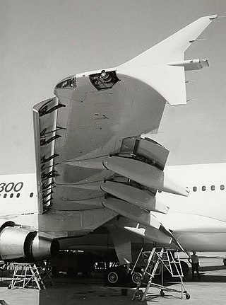
A slat is an aerodynamic surface on the leading edge of the wing of a fixed-wing aircraft. When retracted, the slat lies flush with the rest of the wing. A slat is deployed by sliding forward, opening a slot between the wing and the slat. Air from below the slat flows through the slot and replaces the boundary layer that has travelled at high speed around the leading edge of the slat, losing a significant amount of its kinetic energy due to skin friction drag. When deployed, slats allow the wings to operate at a higher angle of attack before stalling. With slats deployed an aircraft can fly at slower speeds, allowing it to take off and land in shorter distances. They are used during takeoff and landing and while performing low-speed maneuvers which may take the aircraft close to a stall. Slats are retracted in normal flight to minimize drag.
The Akaflieg Darmstadt D-30 Cirrus was an aerodynamically advanced single seat sailplane with a very high aspect ratio wing and a pod and boom fuselage. Built in Germany just before World War II, it was intended as a record breaker and duly set a new world out-and-return distance record in 1938.

