Device increasing the lift of the wing at low speed (take-off and landing)
A slat is an aerodynamic surface on the leading edge of the wing of a fixed-wing aircraft. When retracted, the slat lies flush with the rest of the wing. A slat is deployed by sliding forward, opening a slot between the wing and the slat. Air from below the slat flows through the slot and replaces the boundary layer that has travelled at high speed around the leading edge of the slat, losing a significant amount of its kinetic energy due to skin friction drag. When deployed, slats allow the wings to operate at a higher angle of attack before stalling. With slats deployed an aircraft can fly at slower speeds, allowing it to take off and land in shorter distances. They are used during takeoff and landing and while performing low-speed maneuvers which may take the aircraft close to a stall. Slats are retracted in normal flight to minimize drag.
Slats are high-lift devices typically used on aircraft intended to operate within a wide range of speeds. Trailing-edge flap systems running along the trailing edge of the wing are common on all aircraft.
The spring-loaded slat lies flush with the wing leading edge, held in place by the force of the air acting on them. As the aircraft slows down, the aerodynamic force is reduced and the springs extend the slats. Sometimes referred to as Handley-Page slats.
Fixed
The slat is permanently extended. This is sometimes used on specialist low-speed aircraft (these are referred to as slots) or when simplicity takes precedence over speed.
Powered
The slat extension can be controlled by the pilot. This is commonly used on airliners.
Operation
The chord of the slat is typically only a few percent of the wing chord. The slats may extend over the outer third of the wing, or they may cover the entire leading edge. Many early aerodynamicists, including Ludwig Prandtl, believed that slats work by inducing a high energy stream to the flow of the main airfoil, thus re-energizing its boundary layer and delaying stall.[1] In reality, the slat does not give the air in the slot a high velocity (it actually reduces its velocity) and also it cannot be called high-energy air since all the air outside the actual boundary layers has the same total heat. The actual effects of the slat are:[2][3]
The slat effect
The velocities at the leading edge of the downstream element (main airfoil) are reduced due to the circulation of the upstream element (slat) thus reducing the pressure peaks of the downstream element.
The circulation effect
The circulation of the downstream element increases the circulation of the upstream element thus improving its aerodynamic performance.
The dumping effect
The discharge velocity at the trailing edge of the slat is increased due to the circulation of the main airfoil thus alleviating separation problems or increasing lift.
Off the surface pressure recovery
The deceleration of the slat wake occurs in an efficient manner, out of contact with a wall.
Fresh boundary layer effect
Each new element starts with a fresh boundary layer at its leading edge. Thin boundary layers can withstand stronger adverse gradients than thick ones.[3]
The slat has a counterpart found in the wings of some birds, the alula, a feather or group of feathers which the bird can extend under control of its "thumb".
History
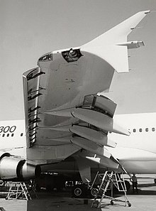
A319 slats during and after landing
Slats were first developed by Gustav Lachmann in 1918. The stall-related crash in August 1917 of a Rumpler C aeroplane prompted Lachmann to develop the idea, and a small wooden model was built in 1917 in Cologne. In Germany in 1918 Lachmann presented a patent for leading-edge slats.[4] However, the German patent office at first rejected it, as the office did not believe the possibility of postponing the stall by dividing the wing.
Independently of Lachmann, Handley Page Ltd in Great Britain also developed the slotted wing as a way to postpone the stall by delaying separation of the flow from the upper surface of the wing at high angles of attack, and applied for a patent in 1919; to avoid a patent challenge, they reached an ownership agreement with Lachmann. That year, an Airco DH.9 was fitted with slats and test flown.[5] Later, an Airco DH.9A was modified as a monoplane with a large wing fitted with full-span leading edge slats and trailing-edge ailerons (i.e. what would later be called trailing-edge flaps) that could be deployed in conjunction with the leading-edge slats to test improved low-speed performance. This was later known as the Handley Page H.P.20[6] Several years later, having subsequently taken employment at the Handley-Page aircraft company, Lachmann was responsible for a number of aircraft designs, including the Handley Page Hampden.
Licensing the design became one of the company's major sources of income in the 1920s. The original designs were in the form of a fixed slot near the leading edge of the wing, a design that was used on a number of STOL aircraft.
During World War II, German aircraft commonly fitted a more advanced version of the slat that reduced drag by being pushed back flush against the leading edge of the wing by air pressure, popping out when the angle of attack increased to a critical angle. Notable slats of that time belonged to the German Fieseler Fi 156Storch. These were similar in design to retractable slats, but were fixed and non-retractable. This design feature allowed the aircraft to takeoff into a light wind in less than 45m (150ft), and land in 18m (60ft). Aircraft designed by the Messerschmitt company employed automatic, spring-loaded leading-edge slats as a general rule, except for the Alexander Lippisch-designed Messerschmitt Me 163BKomet rocket fighter, which instead used fixed slots built integrally with, and just behind, the wing panel's outer leading edges.
Post-World War II, slats have also been used on larger aircraft and generally operated by hydraulics or electricity. The A-4 Skyhawk slats were spring loaded and deployed by the air load below certain speeds.
Research
Several technology research and development efforts exist to integrate the functions of flight control systems such as ailerons, elevators, elevons, flaps, and flaperons into wings to perform the aerodynamic purpose with the advantages of less: mass, cost, drag, inertia (for faster, stronger control response), complexity (mechanically simpler, fewer moving parts or surfaces, less maintenance), and radar cross-section for stealth. These may be used in many unmanned aerial vehicles (UAVs) and 6th generation fighter aircraft.
One promising approach that could rival slats are flexible wings. In flexible wings, much or all of a wing surface can change shape in flight to deflect air flow. The X-53 Active Aeroelastic Wing is a NASA effort. The adaptive compliant wing is a military and commercial effort.[7][8][9]
↑ Gustav Lachmann - National Advisory Committee for Aeronautics (November 1921). "Experiments with slotted wings"(PDF). Archived from the original(PDF) on 2012-11-29. Retrieved 2018-10-14.
This page is based on this Wikipedia article Text is available under the CC BY-SA 4.0 license; additional terms may apply. Images, videos and audio are available under their respective licenses.