Flight instruments are the instruments in the cockpit of an aircraft that provide the pilot with data about the flight situation of that aircraft, such as altitude, airspeed, vertical speed, heading and much more other crucial information in flight. They improve safety by allowing the pilot to fly the aircraft in level flight, and make turns, without a reference outside the aircraft such as the horizon. Visual flight rules (VFR) require an airspeed indicator, an altimeter, and a compass or other suitable magnetic direction indicator. Instrument flight rules (IFR) additionally require a gyroscopic pitch-bank, direction and rate of turn indicator, plus a slip-skid indicator, adjustable altimeter, and a clock. Flight into instrument meteorological conditions (IMC) require radio navigation instruments for precise takeoffs and landings.

In fluid dynamics, a stall is a reduction in the lift coefficient generated by a foil as angle of attack exceeds its critical value. The critical angle of attack is typically about 15°, but it may vary significantly depending on the fluid, foil – including its shape, size, and finish – and Reynolds number.
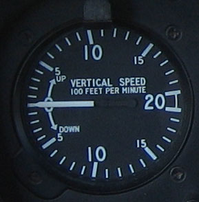
In aviation, a variometer – also known as a rate of climb and descent indicator (RCDI), rate-of-climb indicator, vertical speed indicator (VSI), or vertical velocity indicator (VVI) – is one of the flight instruments in an aircraft used to inform the pilot of the rate of descent or climb. It can be calibrated in metres per second, feet per minute or knots, depending on country and type of aircraft. It is typically connected to the aircraft's external static pressure source.

With respect to aircraft performance, a ceiling is the maximum density altitude an aircraft can reach under a set of conditions, as determined by its flight envelope.

In aviation, airspeed is the speed of an aircraft relative to the air it is flying through. It is difficult to measure the exact airspeed of the aircraft, but other measures of airspeed, such as indicated airspeed and Mach number give useful information about the capabilities and limitations of airplane performance. The common measures of airspeed are:

The true airspeed of an aircraft is the speed of the aircraft relative to the air mass through which it is flying. The true airspeed is important information for accurate navigation of an aircraft. Traditionally it is measured using an analogue TAS indicator, but as GPS has become available for civilian use, the importance of such air-measuring instruments has decreased. Since indicated, as opposed to true, airspeed is a better indicator of margin above the stall, true airspeed is not used for controlling the aircraft; for these purposes the indicated airspeed – IAS or KIAS – is used. However, since indicated airspeed only shows true speed through the air at standard sea level pressure and temperature, a TAS meter is necessary for navigation purposes at cruising altitude in less dense air. The IAS meter reads very nearly the TAS at lower altitude and at lower speed. On jet airliners the TAS meter is usually hidden at speeds below 200 knots (370 km/h). Neither provides for accurate speed over the ground, since surface winds or winds aloft are not taken into account.
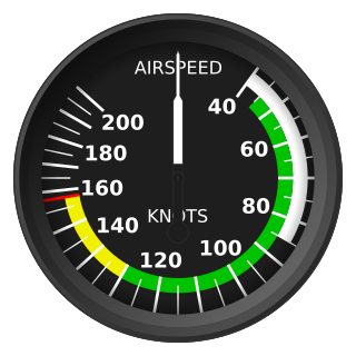
Indicated airspeed (IAS) is the airspeed of an aircraft as measured by its pitot-static system and displayed by the airspeed indicator (ASI). This is the pilots' primary airspeed reference.
In aviation, equivalent airspeed (EAS) is calibrated airspeed (CAS) corrected for the compressibility of air at a non-trivial Mach number. It is also the airspeed at sea level in the International Standard Atmosphere at which the dynamic pressure is the same as the dynamic pressure at the true airspeed (TAS) and altitude at which the aircraft is flying. In low-speed flight, it is the speed which would be shown by an airspeed indicator with zero error. It is useful for predicting aircraft handling, aerodynamic loads, stalling etc.
In aviation, calibrated airspeed (CAS) is indicated airspeed corrected for instrument and position error.
Position error is one of the errors affecting the systems in an aircraft for measuring airspeed and altitude. It is not practical or necessary for an aircraft to have an airspeed indicating system and an altitude indicating system that are exactly accurate. A small amount of error is tolerable. It is caused by the location of the static vent that supplies air pressure to the airspeed indicator and altimeter; there is no position on an aircraft where, at all angles of attack, the static pressure is always equal to atmospheric pressure.
Retreating blade stall is a hazardous flight condition in helicopters and other rotary wing aircraft, where the retreating rotor blade has a lower relative blade speed, combined with an increased angle of attack, causing a stall and loss of lift. Retreating blade stall is the primary limiting factor of a helicopter's never exceed speed, VNE.

A pitot–static system is a system of pressure-sensitive instruments that is most often used in aviation to determine an aircraft's airspeed, Mach number, altitude, and altitude trend. A pitot–static system generally consists of a pitot tube, a static port, and the pitot–static instruments. Other instruments that might be connected are air data computers, flight data recorders, altitude encoders, cabin pressurization controllers, and various airspeed switches. Errors in pitot–static system readings can be extremely dangerous as the information obtained from the pitot static system, such as altitude, is potentially safety-critical. Several commercial airline disasters have been traced to a failure of the pitot–static system.
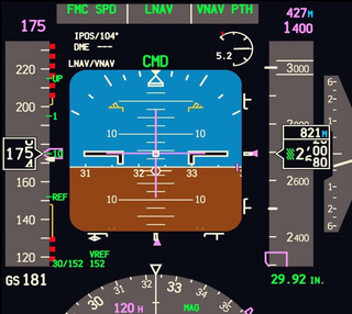
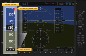
A primary flight display or PFD is a modern aircraft instrument dedicated to flight information. Much like multi-function displays, primary flight displays are built around a Liquid-crystal display or CRT display device. Representations of older six pack or "steam gauge" instruments are combined on one compact display, simplifying pilot workflow and streamlining cockpit layouts.

Birgenair Flight 301 was a flight chartered by Turkish-managed Birgenair partner Alas Nacionales from Puerto Plata in the Dominican Republic to Frankfurt, Germany, via Gander, Canada, and Berlin, Germany. On 6 February 1996, the Boeing 757-200 operating the route crashed shortly after take-off from Puerto Plata's Gregorio Luperón International Airport, killing all 189 people on board. The cause was pilot error after receiving incorrect airspeed information from one of the pitot tubes, which investigators believe was blocked by a wasp nest built inside it. The aircraft had been sitting unused for 20 days, and without pitot tube covers in place for the preceding two days before the crash.

A Machmeter is an aircraft pitot-static system flight instrument that shows the ratio of the true airspeed to the speed of sound, a dimensionless quantity called Mach number. This is shown on a Machmeter as a decimal fraction. An aircraft flying at the speed of sound is flying at a Mach number of one, expressed as Mach 1.

The yaw string, also known as a slip string, is a simple device for indicating a slip or skid in an aircraft in flight. It performs the same function as the slip-skid indicator ball, but is more sensitive, and does not require the pilot to look down at the instrument panel. Technically, it measures sideslip angle, not yaw angle, but this indicates how the aircraft must be yawed to return the sideslip angle to zero.
Austral Líneas Aéreas Flight 2553 was an Argentine domestic scheduled passenger flight from Posadas to Buenos Aires. On October 10, 1997, the McDonnell Douglas DC-9-32 that was operating the flight crashed on the lands of Estancia Magallanes, Nuevo Berlín, 32 kilometres away from Fray Bentos, Uruguay. All 74 passengers and crew died upon impact. The accident remains the deadliest in Uruguayan history.

Coffin corner is the region of flight where a fast but subsonic fixed-wing aircraft's stall speed is near the critical Mach number, at a given gross weight and G-force loading. In this region of flight, it is very difficult to keep an airplane in stable flight. Because the stall speed is the minimum speed required to maintain level flight, any reduction in speed will cause the airplane to stall and lose altitude. Because the critical Mach number is the maximum speed at which air can travel over the wings without losing lift due to flow separation and shock waves, any increase in speed will cause the airplane to lose lift, or to pitch heavily nose-down, and lose altitude.
The minimum control speed (VMC) of a multi-engine aircraft is a V-speed that specifies the calibrated airspeed below which directional or lateral control of the aircraft can no longer be maintained, after the failure of one or more engines. The VMC only applies if at least one engine is still operative, and will depend on the stage of flight. Indeed, multiple VMCs have to be calculated for landing, air travel, and ground travel, and there are more still for aircraft with four or more engines. These are all included in the aircraft flight manual of all multi-engine aircraft. When design engineers are sizing an airplane's vertical tail and flight control surfaces, they have to take into account the effect this will have on the airplane's minimum control speeds.
This is a glossary of acronyms, initialisms and terms used for gliding and soaring. This is a specialized subset of broader aviation, aerospace, and aeronautical terminology. Additional definitions can be found in the FAA Glider Flying Handbook.