
Flight instruments are the instruments in the cockpit of an aircraft that provide the pilot with data about the flight situation of that aircraft, such as altitude, airspeed, vertical speed, heading and much more other crucial information in flight. They improve safety by allowing the pilot to fly the aircraft in level flight, and make turns, without a reference outside the aircraft such as the horizon. Visual flight rules (VFR) require an airspeed indicator, an altimeter, and a compass or other suitable magnetic direction indicator. Instrument flight rules (IFR) additionally require a gyroscopic pitch-bank, direction and rate of turn indicator, plus a slip-skid indicator, adjustable altimeter, and a clock. Flight into instrument meteorological conditions (IMC) require radio navigation instruments for precise takeoffs and landings.

A cockpit or flight deck is the area, on the front part of an aircraft, spacecraft, or submersible, from which a pilot controls the vehicle.

In aviation, the instrument landing system (ILS) is a precision radio navigation system that provides short-range guidance to aircraft to allow them to approach a runway at night or in bad weather. In its original form, it allows an aircraft to approach until it is 200 feet (61 m) over the ground, within a 1⁄2 mile (800 m) of the runway. At that point the runway should be visible to the pilot; if it is not, they perform a missed approach. Bringing the aircraft this close to the runway dramatically increases the range of weather conditions in which a safe landing can be made. Other versions of the system, or "categories", have further reduced the minimum altitudes, runway visual ranges (RVRs), and transmitter and monitoring configurations designed depending on the normal expected weather patterns and airport safety requirements.
The heading indicator (HI), also known as a directional gyro (DG) or direction indicator (DI), is a flight instrument used in an aircraft to inform the pilot of the aircraft's heading.

The attitude indicator (AI), also known as the gyro horizon or artificial horizon, is a flight instrument that informs the pilot of the aircraft orientation relative to Earth's horizon, and gives an immediate indication of the smallest orientation change. The miniature aircraft and horizon bar mimic the relationship of the aircraft relative to the actual horizon. It is a primary instrument for flight in instrument meteorological conditions.
The basic principles of air navigation are identical to general navigation, which includes the process of planning, recording, and controlling the movement of a craft from one place to another.

A non-directional beacon (NDB) or non-directional radio beacon is a radio beacon which does not include inherent directional information. Radio beacons are radio transmitters at a known location, used as an aviation or marine navigational aid. NDB are in contrast to directional radio beacons and other navigational aids, such as low-frequency radio range, VHF omnidirectional range (VOR) and tactical air navigation system (TACAN).

An automatic direction finder (ADF) is a marine or aircraft radio-navigation instrument that automatically and continuously displays the relative bearing from the ship or aircraft to a suitable radio station. ADF receivers are normally tuned to aviation or marine NDBs operating in the LW band between 190 – 535 kHz. Like RDF units, most ADF receivers can also receive medium wave (AM) broadcast stations, though these are less reliable for navigational purposes.

Very High Frequency Omnidirectional Range Station (VOR) is a type of short-range VHF radio navigation system for aircraft, enabling aircraft with a VOR receiver to determine the azimuth, referenced to magnetic north, between the aircraft to/from fixed VOR ground radio beacons. VOR and the first DME(1950) system to provide the slant range distance, were developed in the United States as part of a U.S. civil/military programm for Aeronautical Navigation Aids in 1945. Deployment of VOR and DME(1950) began in 1949 by the U.S. CAA. ICAO standardized VOR and DME(1950) in 1950 in ICAO Annex ed.1. Frequencies for the use of VOR are standardized in the very high frequency (VHF) band between 108.00 and 117.95 MHz Chapter 3, Table A. To improve azimuth accuracy of VOR even under difficult siting conditions, Doppler VOR (DVOR) was developed in the 1960s. VOR is according to ICAO rules a primary means navigation system for commercial and general aviation, (D)VOR are gradually decommissioned and replaced by DME-DME RNAV 7.2.3 and satellite based navigation systems such as GPS in the early 21st century. In 2000 there were about 3,000 VOR stations operating around the world, including 1,033 in the US, but by 2013 the number in the US had been reduced to 967. The United States is decommissioning approximately half of its VOR stations and other legacy navigation aids as part of a move to performance-based navigation, while still retaining a "Minimum Operational Network" of VOR stations as a backup to GPS. In 2015, the UK planned to reduce the number of stations from 44 to 19 by 2020.

An instrument landing system localizer, or simply localizer, is a system of horizontal guidance in the instrument landing system, which is used to guide aircraft along the axis of the runway.
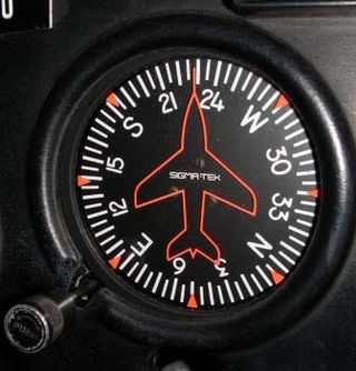
In aviation, aircraft compass turns are turns made in an aircraft using only a magnetic compass for guidance.

In aviation, an electronic flight instrument system (EFIS) is a flight instrument display system in an aircraft cockpit that displays flight data electronically rather than electromechanically. An EFIS normally consists of a primary flight display (PFD), multi-function display (MFD), and an engine indicating and crew alerting system (EICAS) display. Early EFIS models used cathode-ray tube (CRT) displays, but liquid crystal displays (LCD) are now more common. The complex electromechanical attitude director indicator (ADI) and horizontal situation indicator (HSI) were the first candidates for replacement by EFIS. Now, however, few flight deck instruments cannot be replaced by an electronic display.

In aviation, an instrument approach or instrument approach procedure (IAP) is a series of predetermined maneuvers for the orderly transfer of an aircraft operating under instrument flight rules from the beginning of the initial approach to a landing, or to a point from which a landing may be made visually. These approaches are approved in the European Union by EASA and the respective country authorities and in the United States by the FAA or the United States Department of Defense for the military. The ICAO defines an instrument approach as "a series of predetermined maneuvers by reference to flight instruments with specific protection from obstacles from the initial approach fix, or where applicable, from the beginning of a defined arrival route to a point from which a landing can be completed and thereafter, if landing is not completed, to a position at which holding or en route obstacle clearance criteria apply."

The basic fluxgate compass is a simple electromagnetic device that employs two or more small coils of wire around a core of highly permeable magnetic material, to directly sense the direction of the horizontal component of the Earth's magnetic field. The advantages of this mechanism over a magnetic compass are that the reading is in electronic form and can be digitised and transmitted easily, displayed remotely, and used by an electronic autopilot for course correction.
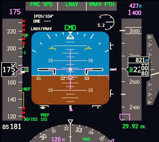
A primary flight display or PFD is a modern aircraft instrument dedicated to flight information. Much like multi-function displays, primary flight displays are built around a Liquid-crystal display or CRT display device. Representations of older six pack or "steam gauge" instruments are combined on one compact display, simplifying pilot workflow and streamlining cockpit layouts.
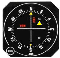
A course deviation indicator (CDI) is an avionics instrument used in aircraft navigation to determine an aircraft's lateral position in relation to a course to or from a radio navigation beacon. If the location of the aircraft is to the left of this course, the needle deflects to the right, and vice versa.
In aviation, a flight director (FD) is a flight instrument that is overlaid on the attitude indicator that shows the pilot of an aircraft the attitude required to execute the desired flight path. Flight directors are mostly commonly used during approach and landing. They can be used with or without autopilot systems.

The yaw string, also known as a slip string, is a simple device for indicating a slip or skid in an aircraft in flight. It performs the same function as the slip-skid indicator ball, but is more sensitive, and does not require the pilot to look down at the instrument panel. Technically, it measures sideslip angle, not yaw angle, but this indicates how the aircraft must be yawed to return the sideslip angle to zero.

First Air Flight 6560 was a domestic charter flight that crashed on landing at Resolute, Nunavut, Canada, on 20 August 2011. Of the 15 people on board, 12 were killed and the remaining three were severely injured. The Boeing 737-200 of First Air was operating a service from Yellowknife, Northwest Territories, when it struck a hill obscured by clouds near Resolute Bay Airport.
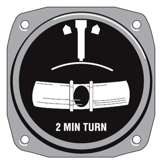
In aviation, the turn and slip indicator and the turn coordinator (TC) variant are essentially two aircraft flight instruments in one device. One indicates the rate of turn, or the rate of change in the aircraft's heading; the other part indicates whether the aircraft is in coordinated flight, showing the slip or skid of the turn. The slip indicator is actually an inclinometer that at rest displays the angle of the aircraft's transverse axis with respect to horizontal, and in motion displays this angle as modified by the acceleration of the aircraft. The most commonly used units are degrees per second (deg/s) or minutes per turn (min/tr).


