The systems described below are specific to current production Boeing airliners, although the details are essentially identical for passenger jets from Airbus and other companies. An exception was Concorde which had a supplementary air supply system fitted due to the higher altitudes at which it flew, and also the slightly higher cabin pressure it employed.[1]
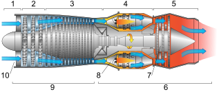
Environmental control system (ECS) schematic of Boeing 737-300
On jetliners, air is supplied to the ECS by being bled from a compressor stage of each gas turbine engine, upstream of the combustor. The temperature and pressure of this bleed air varies according to which compressor stage is used, and the power setting of the engine. A manifold pressure regulating shut-off valve (MPRSOV) restricts the flow as necessary to maintain the desired pressure for downstream systems.
A certain minimum supply pressure is needed to drive the air through the system, but it is desired to use as low a supply pressure as possible, because the energy the engine uses to compress the bleed air is not available for propulsion, and fuel consumption suffers. For this reason, air is commonly drawn from one of two (or in some cases such as the Boeing 777, three) bleed ports at different compressor stage locations. When the engine is at low pressure (low thrust or high altitude), the air is drawn from the highest pressure bleed port. As pressure is increased (more thrust or lower altitude) and reaches a predetermined crossover point, the high pressure shut-off valve (HPSOV) closes and air is selected from a lower pressure port to minimize the fuel performance loss. The reverse happens as engine pressure decreases.
To achieve the desired temperature, the bleed-air is passed through a heat exchanger called a pre-cooler. Air bled from the engine fan is blown across the pre-cooler, located in the engine strut, and absorbs excess heat from the service bleed air. A fan air modulating valve (FAMV) varies the cooling airflow to control the final air temperature of the service bleed air.
Notably, the Boeing 787 does not use bleed air to pressurize the cabin. The aircraft instead draws air from dedicated inlets, located ahead of the wings. [2][3]
An ACM uses no Freon: the air itself is the refrigerant. The ACM is preferred over vapor cycle devices because of reduced weight and maintenance requirements.
Most jetliners are equipped with PACKs Meaning of abbreviation see here. The location of the air conditioning (AC) PACK(s) depends on the design of the aircraft. In some designs, they are installed in the wing-to-body fairing between the two wings beneath the fuselage. On other aircraft (Douglas AircraftDC-9 Series) the AC PACKs are located in the tail. The aircraft PACKs on the McDonnell Douglas DC-10/MD-11 and Lockheed L-1011 are located in the front of the aircraft beneath the flight deck. Nearly all jetliners have two PACKs, although larger aircraft such as the Boeing 747, Lockheed L-1011, and McDonnell-Douglas DC-10/MD-11 have three.
The quantity of bleed air flowing to the AC pack is regulated by the flow control valve (FCV). One FCV is installed for each PACK. A normally closed isolation valve prevents air from the left bleed system from reaching the right PACK (and vice versa), although this valve may be opened in the event of loss of one bleed system.
Downstream of the FCV is the cold-air unit (CAU), also referred to as the refrigeration unit. There are many various types of CAUs; however, they all use typical fundamentals. The bleed air enters the primary ram-air heat exchanger, where it is cooled by either ram air, expansion or a combination of both. The cold air then enters the compressor, where it is repressurized, which reheats the air. A pass through the secondary ram-air heat exchanger cools the air while maintaining the high pressure. The air then passes through a turbine which expands the air to further reduce heat. Similar in operation to a turbo-charger unit, the compressor and turbine are on a single shaft. The energy extracted from the air passing through the turbine is used to power the compressor. The air flow then is directed to the reheater before it passes to the condenser to be ready for water extraction by water extractor.[4]
The air is then sent through a water separator, where the air is forced to spiral along its length and centrifugal forces cause the moisture to be flung through a sieve and toward the outer walls where it is channeled toward a drain and sent overboard. Then, the air usually will pass through a water separator coalescer or the sock. The sock retains the dirt and oil from the engine bleed air to keep the cabin air cleaner. This water removal process prevents ice from forming and clogging the system, and keeps the cockpit and cabin from fogging on ground operation and low altitudes.
For a sub-zero bootstrap CAU, the moisture is extracted before it reaches the turbine so that sub-zero temperatures may be reached.
The temperature of the PACK outlet air is controlled by the adjusting flow through the ram-air system (below), and modulating a temperature control valve (TCV) which bypasses a portion of the hot bleed air around the ACM and mixes it with the cold air downstream of the ACM turbine.
Ram air system
The ram-air inlet is a small scoop, generally located on the wing-to-body fairing. Nearly all jetliners use a modulating door on the ram-air inlet to control the amount of cooling airflow through the primary and secondary ram air heat exchangers.
To increase ram-air recovery, nearly all jetliners use modulating vanes on the ram-air exhaust. A ram-air fan within the ram system provides ram-air flow across the heat exchangers when the aircraft is on the ground. Nearly all modern fixed-wing aircraft use a fan on a common shaft with the ACM, powered by the ACM turbine.
Air distribution
The AC PACK exhaust air is ducted into the pressurized fuselage, where it is mixed with filtered air from the recirculation fans, and fed into the mix manifold. On nearly all modern jetliners, the airflow is approximately 50% outside air and 50% filtered air.
Modern jetliners use high-efficiency particulate arresting HEPA filters, which trap more than 99% of all bacteria and clustered viruses.
Air from the mix manifold is directed to overhead distribution nozzles[5] in the various zones of the aircraft. Temperature in each zone may be adjusted by adding small amounts of trim air, which is low-pressure, high-temperature air tapped off the AC PACK upstream of the TCV. Air is also supplied to individual gasper vents.[lower-alpha 1] A revolving control on the vent can be turned to adjust ventilation between no air output at all and a fairly substantial breeze.
Gasper vent over passenger seats of a Boeing 737-800
Gaspers[lower-alpha 1] usually receive their air from the AC PACKs aboard the aircraft, which in turn receive compressed, clean air from the compressor stages of the aircraft's jet engines or when on the ground from the auxiliary power unit (APU) or a ground source. A master control for gaspers is located in the cockpit; gaspers are often temporarily turned off during certain phases of flight (e.g. during take-off and climb) when the load on the engines from bleed-air demands must be minimized.
Airflow into the fuselage is approximately constant, and pressure is maintained by varying the opening of the out-flow valve (OFV). Most modern jetliners have a single OFV located near the bottom aft end of the fuselage, although some larger aircraft like the Boeing747 and 777 have two.
In the event the OFV should fail closed, at least two positive pressure relief valves (PPRV) and at least one negative pressure relief valve (NPRV) are provided to protect the fuselage from over- and under- pressurization.
Aircraft cabin pressure is commonly pressurized to a cabin altitude of 8000feet or less. That means that the pressure is 10.9 pounds per square inch (75kPa), which is the ambient pressure at 8,000 feet (2,400m). Note that a lower cabin altitude is a higher pressure. The cabin pressure is controlled by a cabin pressure schedule, which associates each aircraft altitude with a cabin altitude. The new airliners such as the Airbus A350 and Boeing 787 will have lower maximum cabin altitudes which help in passenger fatigue reduction during flights.
The atmosphere at typical jetliner cruising altitudes is generally very dry and cold; the outside air pumped into the cabin on a long flight has the potential to cause condensation which might in turn cause corrosion or electrical faults, and is thus eliminated. Consequently, when humid air at lower altitudes is encountered and drawn in, the ECS dries it through the warming and cooling cycle and the water separator mentioned above, so that even with high external relative humidity, inside the cabin it will usually be not much higher than 10% relative humidity.
Although low cabin humidity has health benefits of preventing the growth of fungus and bacteria, the low humidity causes drying of the skin, eyes and mucosal membranes and contributes to dehydration, leading to fatigue, discomfort and health issues. In one study the majority of flight attendants reported discomfort and health issues from low humidity.[6] In a statement to US Congress in 2003 a member of the Committee on Air Quality in Passenger Cabins of Commercial Aircraft said "low relative humidity might cause some temporary discomfort (e.g., drying eyes, nasal passages, and skin), but other possible short- or long-term effects have not been established".[7]
A cabin humidity control system may be added to the ECS of some aircraft to keep relative humidity from extremely low levels, consistent with the need to prevent condensation.[8] Furthermore, the Boeing787 and AirbusA350, by using more corrosion-resistant composites in their construction, can operate with a cabin relative humidity of 16% on long flights.
The bleed air comes from the engines but is bled from the engine upstream of the combustor. Air cannot flow backwards through the engine except during a compressor stall (essentially a jet engine backfire), thus the bleed air should be free of combustion contaminants from the normal running of the aircraft's own engines.
However, on occasions carbon seals can leak oil (containing potentially hazardous chemicals) into the bleed air, in what is known in the industry as a fume event.[9] This is generally dealt with quickly since failed oil seals will reduce the engine life.
Oil contamination from this and other sources within the engine bay has led to health concerns from some advocacy groups and has triggered research by several academic institutions and regulatory agencies. However, no credible research has yielded evidence for the existence of a medical condition caused by fume events.[10][11][12]
Footnotes
1 2 Gaspers are small, circular vents above each passenger seat that can be adjusted by passengers for their personal comfort.
Related Research Articles
A ramjet is a form of airbreathing jet engine that requires forward motion of the engine to provide air for combustion. Ramjets work most efficiently at supersonic speeds around Mach 3 and can operate up to Mach 6.
An auxiliary power unit (APU) is a device on a vehicle that provides energy for functions other than propulsion. They are commonly found on large aircraft and naval ships as well as some large land vehicles. Aircraft APUs generally produce 115 V AC voltage at 400 Hz, to run the electrical systems of the aircraft; others can produce 28 V DC voltage. APUs can provide power through single or three-phase systems.
A turbofan or fanjet is a type of airbreathing jet engine that is widely used in aircraft propulsion. The word "turbofan" is a combination of the preceding generation engine technology of the turbojet, and a reference to the additional fan stage added. It consists of a gas turbine engine which achieves mechanical energy from combustion, and a ducted fan that uses the mechanical energy from the gas turbine to force air rearwards. Thus, whereas all the air taken in by a turbojet passes through the combustion chamber and turbines, in a turbofan some of that air bypasses these components. A turbofan thus can be thought of as a turbojet being used to drive a ducted fan, with both of these contributing to the thrust.
The turbojet is an airbreathing jet engine which is typically used in aircraft. It consists of a gas turbine with a propelling nozzle. The gas turbine has an air inlet which includes inlet guide vanes, a compressor, a combustion chamber, and a turbine. The compressed air from the compressor is heated by burning fuel in the combustion chamber and then allowed to expand through the turbine. The turbine exhaust is then expanded in the propelling nozzle where it is accelerated to high speed to provide thrust. Two engineers, Frank Whittle in the United Kingdom and Hans von Ohain in Germany, developed the concept independently into practical engines during the late 1930s.
The General Electric GEnx is an advanced dual rotor, axial flow, high-bypass turbofan jet engine in production by GE Aerospace for the Boeing 747-8 and 787. The GEnx succeeded the CF6 in GE's product line.
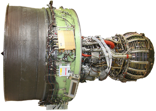
Bleed air in aerospace engineering is compressed air taken from the compressor stage of a gas turbine, upstream of its fuel-burning sections. Automatic air supply and cabin pressure controller (ASCPC) valves bleed air from low or high stage engine compressor sections; low stage air is used during high power setting operation, and high stage air is used during descent and other low power setting operations. Bleed air from that system can be utilized for internal cooling of the engine, cross-starting another engine, engine and airframe anti-icing, cabin pressurization, pneumatic actuators, air-driven motors, pressurizing the hydraulic reservoir, and waste and water storage tanks. Some engine maintenance manuals refer to such systems as "customer bleed air".
The Pratt & Whitney J58 is an American jet engine that powered the Lockheed A-12, and subsequently the YF-12 and the SR-71 aircraft. It was an afterburning turbojet engine with a unique compressor bleed to the afterburner that gave increased thrust at high speeds. Because of the wide speed range of the aircraft, the engine needed two modes of operation to take it from stationary on the ground to 2,000 mph (3,200 km/h) at altitude. It was a conventional afterburning turbojet for take-off and acceleration to Mach 2 and then used permanent compressor bleed to the afterburner above Mach 2. The way the engine worked at cruise led it to be described as "acting like a turboramjet". It has also been described as a turboramjet based on incorrect statements describing the turbomachinery as being completely bypassed.
Cabin pressurization is a process in which conditioned air is pumped into the cabin of an aircraft or spacecraft in order to create a safe and comfortable environment for humans flying at high altitudes. For aircraft, this air is usually bled off from the gas turbine engines at the compressor stage, and for spacecraft, it is carried in high-pressure, often cryogenic, tanks. The air is cooled, humidified, and mixed with recirculated air by one or more environmental control systems before it is distributed to the cabin.
An air cycle machine (ACM) is the refrigeration unit of the environmental control system (ECS) used in pressurized gas turbine-powered aircraft. Normally an aircraft has two or three of these ACM. Each ACM and its components are often referred as an air conditioning pack. The air cycle cooling process uses air instead of a phase changing material such as Freon in the gas cycle. No condensation or evaporation of a refrigerant is involved, and the cooled air output from the process is used directly for cabin ventilation or for cooling electronic equipment.
A compressor stall is a local disruption of the airflow in the compressor of a gas turbine or turbocharger. A stall that results in the complete disruption of the airflow through the compressor is referred to as a compressor surge. The severity of the phenomenon ranges from a momentary power drop barely registered by the engine instruments to a complete loss of compression in case of a surge, requiring adjustments in the fuel flow to recover normal operation.
An intake is an opening, structure or system through which a fluid is admitted to a space or machine as a consequence of a pressure differential between the outside and the inside. The pressure difference may be generated on the inside by a mechanism, or on the outside by ram pressure or hydrostatic pressure. Flow rate through the intake depends on pressure difference, fluid properties, and intake geometry.
The Learjet 25 is an American ten-seat, twin-engine, high-speed business jet aircraft manufactured by Learjet. It is a stretched version of the Learjet 24.
A compressor map is a chart which shows the performance of a turbomachinery compressor. This type of compressor is used in gas turbine engines, for supercharging reciprocating engines and for industrial processes, where it is known as a dynamic compressor. A map is created from compressor rig test results or predicted by a special computer program. Alternatively the map of a similar compressor can be suitably scaled. This article is an overview of compressor maps and their different applications and also has detailed explanations of maps for a fan and intermediate and high-pressure compressors from a three-shaft aero-engine as specific examples.
A jet engine performs by converting fuel into thrust. How well it performs is an indication of what proportion of its fuel goes to waste. It transfers heat from burning fuel to air passing through the engine. In doing so it produces thrust work when propelling a vehicle but a lot of the fuel is wasted and only appears as heat. Propulsion engineers aim to minimize the degradation of fuel energy into unusable thermal energy. Increased emphasis on performance improvements for commercial airliners came in the 1970s from the rising cost of fuel.
The General Electric CJ805 is a jet engine which was developed by General Electric Aircraft Engines in the late 1950s. It was a civilian version of the J79 and differed only in detail. It was developed in two versions. The basic CJ805-3 was a turbojet and powered the Convair 880 airliner, and the CJ805-23 a turbofan derivative which powered the Convair 990 Coronado variant of the 880.
This article briefly describes the components and systems found in jet engines.
An airbreathing jet engine is a jet engine in which the exhaust gas which supplies jet propulsion is atmospheric air, which is taken in, compressed, heated, and expanded back to atmospheric pressure through a propelling nozzle. Compression may be provided by a gas turbine, as in the original turbojet and newer turbofan, or arise solely from the ram pressure of the vehicle's velocity, as with the ramjet and pulsejet.
The General Electric Passport is a turbofan developed by GE Aerospace for large business jets. It was selected in 2010 to power the Bombardier Global 7500 and 8000, first run on June 24, 2013, and first flown in 2015. It was certified in April 2016 and powered the Global 7500 first flight on November 4, 2016, before its 2018 introduction. It produces 14,000 to 20,000 lbf of thrust, a range previously covered by the General Electric CF34. A smaller scaled CFM LEAP, it is a twin-spool axial engine with a 5.6:1 bypass ratio and a 45:1 overall pressure ratio and is noted for its large one-piece 52 in (130 cm) fan 18-blade titanium blisk.
The accessory drive is a gearbox that forms part of a gas turbine engine. Although not part of the engine's core, it drives the accessories – such as generators, pumps for fuel and lubrication oil, air compressors, hydraulic pumps and engine starters – that are otherwise essential for the operation of the engine or the aircraft on which it is mounted. Accessory drives on large engines handle between 400–500 hp.
Nathan C. Price was an American engineer and inventor. He made substantial contributions to several US aircraft projects during the first half of the twentieth century.
↑ Bagshaw, Michael (September 2008). "The Aerotoxic Syndrome"(PDF). European Society of Aerospace Medicine. Archived from the original(PDF) on February 27, 2012. Retrieved December 31, 2012.
↑ Select Committee on Science and Technology (2000). "Chapter 4: Elements Of Healthy Cabin Air". Science and Technology - Fifth Report (Report). House of Lords. Archived from the original on 2010-04-24. Retrieved 2010-07-05.
↑ "Aircraft fumes: The secret life of BAe", "In the back" column, Private Eye magazine, issue 1193, 14–27 September 2007, pages 26–27; Pressdram Ltd., London.
HVAC Applications volume of the ASHRAE Handbook, American Society of Heating, Ventilating and Air-Conditioning Engineers, Inc. (ASHRAE), Atlanta, GA, 1999.
This page is based on this Wikipedia article Text is available under the CC BY-SA 4.0 license; additional terms may apply. Images, videos and audio are available under their respective licenses.