
A vertical take-off and landing (VTOL) aircraft is one that can take off and land vertically without relying on a runway. This classification can include a variety of types of aircraft including helicopters as well as thrust-vectoring fixed-wing aircraft and other hybrid aircraft with powered rotors such as cyclogyros/cyclocopters and gyrodynes.
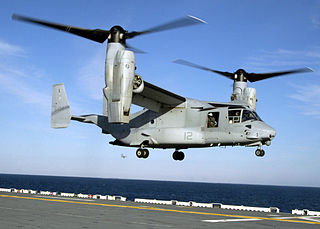
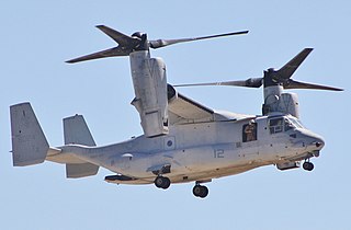
A tiltrotor is an aircraft that generates lift and propulsion by way of one or more powered rotors mounted on rotating shafts or nacelles usually at the ends of a fixed wing. Almost all tiltrotors use a transverse rotor design, with a few exceptions that use other multirotor layouts.

Takeoff is the phase of flight in which an aerospace vehicle leaves the ground and becomes airborne. For aircraft traveling vertically, this is known as liftoff.
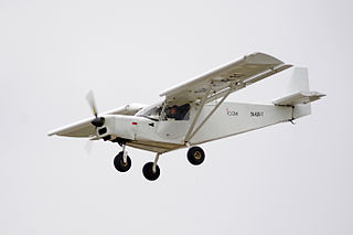
A short takeoff and landing (STOL) aircraft is a conventional fixed-wing aircraft that has short runway requirements for takeoff and landing. Many STOL-designed aircraft also feature various arrangements for use on airstrips with harsh conditions. STOL aircraft, including those used in scheduled passenger airline operations, have also been operated from STOLport airfields which feature short runways.

A vertical and/or short take-off and landing (V/STOL) aircraft is an airplane able to take-off or land vertically or on short runways. Vertical takeoff and landing (VTOL) aircraft are a subset of V/STOL craft that do not require runways at all. Generally, a V/STOL aircraft needs to be able to hover. Helicopters are not considered under the V/STOL classification as the classification is only used for aeroplanes, aircraft that achieve lift (force) in forward flight by planing the air, thereby achieving speed and fuel efficiency that is typically greater than the capability of helicopters.

The Curtiss-Wright X-19, company designation Model 200, was an American experimental tiltrotor aircraft of the early 1960s. It was noteworthy for being the last aircraft of any kind manufactured by Curtiss-Wright.
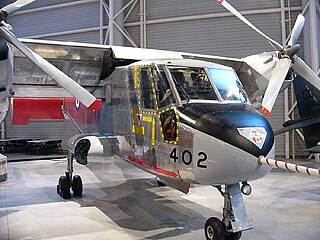
The Canadair CL-84 "Dynavert", designated by the Canadian Forces as the CX-131, was a V/STOL turbine tiltwing monoplane designed and manufactured by Canadair between 1964 and 1972. Only four of these experimental aircraft were built with three entering flight testing. Two of the CL-84s crashed due to mechanical failures, with no fatalities occurring in either of the accidents. Despite the CL-84 being successful in the experimental and operational trials carried out between 1972 and 1974, none of the prospective customers placed any orders for the type.

A gyrodyne is a type of VTOL aircraft with a helicopter rotor-like system that is driven by its engine for takeoff and landing only, and includes one or more conventional propeller or jet engines to provide forward thrust during cruising flight. During forward flight the rotor is unpowered and free-spinning, like an autogyro, and lift is provided by a combination of the rotor and conventional wings. The gyrodyne is one of a number of similar concepts which attempt to combine helicopter-like low-speed performance with conventional fixed-wing high-speeds, including tiltrotors and tiltwings.

A rotorcraft or rotary-wing aircraft is a heavier-than-air aircraft with rotary wings or rotor blades, which generate lift by rotating around a vertical mast. Several rotor blades mounted on a single mast are referred to as a rotor. The International Civil Aviation Organization (ICAO) defines a rotorcraft as "supported in flight by the reactions of the air on one or more rotors".
A convertiplane is defined by the Fédération Aéronautique Internationale as an aircraft which uses rotor power for vertical takeoff and landing (VTOL) and converts to fixed-wing lift in normal flight. In the US it is further classified as a sub-type of powered lift. In popular usage it sometimes includes any aircraft that converts in flight to change its method of obtaining lift.

The Ling-Temco-Vought (LTV) XC-142 is a tiltwing experimental aircraft designed to investigate the operational suitability of vertical/short takeoff and landing (V/STOL) transports. An XC-142A first flew conventionally on 29 September 1964, and completed its first transitional flight on 11 January 1965 by taking off vertically, changing to forward flight, and finally landing vertically. Its service sponsors pulled out of the program one by one, and it eventually ended due to a lack of interest after demonstrating its capabilities successfully.
A powered lift aircraft takes off and lands vertically under engine power but uses a fixed wing for horizontal flight. Like helicopters, these aircraft do not need a long runway to take off and land, but they have a speed and performance similar to standard fixed-wing aircraft in combat or other situations.

A circulation control wing (CCW) is a form of high-lift device for use on the main wing of an aircraft to increase the maximum lift coefficient and reduce the stalling speed. CCW technology has been in the research and development phase for over sixty years. Blown flaps were an early example of CCW.
Deflected slipstream is an approach to creating an aircraft that can take off and land vertically (VTOL), or at least with a very short runway (STOL). The basic principle is to deflect the slipstream from one or more propellers approximately 90 degrees, to create an upward thrust for vertical takeoff and a downward air cushion for landing. Once airborne, the flaps are retracted so the airplane can fly horizontally.
Willard Ray Custer was an American engineer and aircraft visionary, inventor of the channel wing concept.

The Custer CCW-5 was a twin-engined, 5-seat aircraft of pusher configuration, which used a channel wing claimed to enable low speed flight and short take-offs. Two CCW-5s flew, eleven years apart, but the type never entered production.
The Custer Channel Wing was a series of American-built experimental aircraft designs of the 1940s and 1950s incorporating a half-barrel shaped section to each wing.
Aircraft have different ways to take off and land. Conventional airplanes accelerate along the ground until reaching a speed that is sufficient for the airplane to takeoff and climb at a safe speed. Some airplanes can take off at low speed, this being a short takeoff. Some aircraft such as helicopters and Harrier jump jets can take off and land vertically. Rockets also usually take off vertically, but some designs can land horizontally.

The GL-10 Greased Lightning is a hybrid diesel-electric tiltwing unmanned aircraft.

Lift fan is an aircraft configuration in which lifting fans are located in large holes in an otherwise conventional fixed wing or fuselage. It is used for V/STOL operation.


