Leading-edge slot

Last updated
A leading-edge slot on a STOL aircraft Leading edge slot.jpg
A leading-edge slot on a STOL aircraft

A leading-edge slot is a fixed aerodynamic feature of the wing of some aircraft to reduce the stall speed and promote good low-speed handling qualities. A leading-edge slot is a spanwise gap in each wing, allowing air to flow from below the wing to its upper surface. In this manner they allow flight at higher angles of attack and thus reduce the stall speed. [1]

Contents

Purpose and development

Full-span leading-edge slot in the wing of the PZL-104M Wilga 2000 PZL-104M Wilga 2000 of Polish Border Guard (reg. SN-41YG), static display, Radom AirShow 2005, Poland.jpg
Full-span leading-edge slot in the wing of the PZL-104M Wilga 2000

At an angle of attack above about 15° many airfoils enter the stall. Modification of such an airfoil with a fixed leading-edge slot can increase the stalling angle to between 22° and 25°. [2]

Slots were first developed by Handley Page in 1919 and the first aircraft to fly with them was the experimental H.P.17, a modified Airco DH.9A. Their invention is credited jointly to Sir Frederick Handley Page and Gustav Lachmann. The first aircraft fitted with controllable slots was the Handley Page H.P.20. Licensing the design became one of Handley Page's major sources of income in the 1920s. [3]

Similar, but retractable, leading-edge devices are called slats. [4] When the slat opens, it creates a slot between the slat and the remainder of the wing; retracted, the drag is reduced.

A fixed leading-edge slot can increase the maximum lift coefficient of an airfoil section by 40%. In conjunction with a slat, the increase in maximum lift coefficient can be 50% or even 60%. [2] [5]

Unlike trailing edge flaps, leading-edge slots do not increase the lift coefficient at zero angle of attack since they do not alter the camber. [6]

Operation

Partial-span leading-edge slot in the wing of a Stinson 108-3 Stinson108-3photo03.jpg
Partial-span leading-edge slot in the wing of a Stinson 108-3
Fieseler Storch with full-span slots Fieseler Fi156.jpg
Fieseler Storch with full-span slots
A Zenith STOL CH 701 showing its full-span slot. ZenairCH701photo01.JPG
A Zenith STOL CH 701 showing its full-span slot.

A leading-edge slot is a fixed (non-closing) gap behind the wing's leading edge. Air from below the wing can accelerate through the slot towards the low pressure region above the wing, and exit from the slot moving parallel to the upper wing surface. This high-speed flow then mixes with the boundary layer attached to the upper surface and delays boundary layer separation from the upper surface.

Slots naturally exact a penalty on the aircraft in which they are used. This is because they contribute to drag compared to an unslotted wing. [7] The extra drag at low speed is acceptable because of the beneficial reduction in stall speed and improvement in handling characteristics, but at higher speeds the extra drag contributed by slots is a significant disadvantage because it reduces cruising speed and increases fuel consumption per unit distance flown.

One way to reduce the cruise drag of slots is to make them able to be closed. This arrangement is known as leading-edge slats. Aerodynamically, slats work in the same way as fixed slots but slats can be retracted at higher speeds when they are not needed. Slats, in turn, are heavier and more complex than slots. [4] [7]

At low angles of attack the airflow through the slot is insignificant, although it contributes to drag. At progressively higher angles of attack, the flow of air through the slot becomes increasingly significant, accelerating from the higher pressure region below the wing to the lower pressure region on top of the wing. At high angles of attack the fastest airspeed relative to the airfoil is very close to the leading edge, on the upper surface. In this region of high local airspeed, skin friction (viscous force) is very high and the boundary layer arriving at the slot on the upper wing has lost much of its total pressure (or total mechanical energy) due to this friction. In contrast, the air passing through the slot has not experienced this high local airspeed or high skin friction, and its total pressure remains close to the free-stream value. The mixing of the upper surface boundary layer with air arriving through the slot re-energises the boundary layer which then remains attached to the upper surface of the wing to a higher angle of attack than if the slot were not there. [2] The leading-edge slot was therefore one of the earliest forms of boundary layer control. [2]

Application of leading-edge slots

Leading-edge slots are generally of two types: those that are full-span and those that are partial-span. [4]

Full-span slots are generally found on Short Take-off and Landing STOL aircraft like the Fieseler Storch, Dornier Do 27, PZL-104M Wilga 2000, and Zenair CH 701 STOL. Their primary purpose is to allow the aircraft to fly at a higher angle of attack before reaching the stalling angle. [8]

In aircraft other than specialist STOL aircraft, full-span slots have serious drawbacks because, to take advantage of the high angle of attack at the stall, they usually necessitate long undercarriage legs that either cause high drag or are longer than can be accommodated easily inside the airframe. [9]

Partial-span slots are usually found only on the outboard portion of the wing where they ensure airflow over that portion of the wing will remain unstalled at higher angles of attack than the inboard portions of the wing. This ensures the wing root stalls first and contributes to docile stall behaviour and maintaining aileron control throughout the stall. [2] [4] Using slots in this manner produces a similar result to employing washout on a wing, but through a different means. Examples of aircraft with partial-span, fixed slots are the Stinson 108, Bristol Beaufort, Lockheed Hudson, and Dornier Do 28D-2 Skyservant.

See also

Related Research Articles

Lift (force) Force perpendicular to flow of surrounding fluid

A fluid flowing around the surface of an object exerts a force on it. Lift is the component of this force that is perpendicular to the oncoming flow direction. It contrasts with the drag force, which is the component of the force parallel to the flow direction. Lift conventionally acts in an upward direction in order to counter the force of gravity, but it can act in any direction at right angles to the flow.

Wing Surface used for flight, for example by insects, birds, bats and airplanes

A wing is a type of fin that produces lift while moving through air or some other fluid. Accordingly, wings have streamlined cross-sections that are subject to aerodynamic forces and act as airfoils. A wing's aerodynamic efficiency is expressed as its lift-to-drag ratio. The lift a wing generates at a given speed and angle of attack can be one to two orders of magnitude greater than the total drag on the wing. A high lift-to-drag ratio requires a significantly smaller thrust to propel the wings through the air at sufficient lift.

Stall (fluid dynamics) Abrupt reduction in lift due to flow separation

In fluid dynamics, a stall is a reduction in the lift coefficient generated by a foil as angle of attack increases. This occurs when the critical angle of attack of the foil is exceeded. The critical angle of attack is typically about 15°, but it may vary significantly depending on the fluid, foil, and Reynolds number.

Angle of attack

In fluid dynamics, angle of attack is the angle between a reference line on a body and the vector representing the relative motion between the body and the fluid through which it is moving. Angle of attack is the angle between the body's reference line and the oncoming flow. This article focuses on the most common application, the angle of attack of a wing or airfoil moving through air.

Leading-edge extension Anti-stall control surface on aircraft

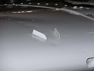
A leading-edge extension (LEX) is a small extension to an aircraft wing surface, forward of the leading edge. The primary reason for adding an extension is to improve the airflow at high angles of attack and low airspeeds, to improve handling and delay the stall. A dog tooth can also improve airflow and reduce drag at higher speeds.

Vortex generator Aerodynamic device

A vortex generator (VG) is an aerodynamic device, consisting of a small vane usually attached to a lifting surface or a rotor blade of a wind turbine. VGs may also be attached to some part of an aerodynamic vehicle such as an aircraft fuselage or a car. When the airfoil or the body is in motion relative to the air, the VG creates a vortex, which, by removing some part of the slow-moving boundary layer in contact with the airfoil surface, delays local flow separation and aerodynamic stalling, thereby improving the effectiveness of wings and control surfaces, such as flaps, elevators, ailerons, and rudders.

Airfoil Cross-sectional shape of a wing, blade of a propeller, rotor, or turbine, or sail

An airfoil or aerofoil is the cross-sectional shape of an object whose motion through a gas is capable of generating significant lift, such as a wing, a sail, or the blades of propeller, rotor, or turbine.

Blown flap

Blown flaps, or jet flaps, are powered aerodynamic high-lift devices used on the wings of certain aircraft to improve their low-speed flight characteristics. They use air blown through nozzles to shape the airflow over the rear edge of the wing, directing the flow downward to increase the lift coefficient. There are a variety of methods to achieve this airflow, most of which use jet exhaust or high-pressure air bled off of a jet engine's compressor and then redirected to follow the line of trailing-edge flaps.

High-lift device Wing surface area adjuster, typically for shortening take-off and landing

In aircraft design and aerospace engineering, a high-lift device is a component or mechanism on an aircraft's wing that increases the amount of lift produced by the wing. The device may be a fixed component, or a movable mechanism which is deployed when required. Common movable high-lift devices include wing flaps and slats. Fixed devices include leading-edge slots, leading edge root extensions, and boundary layer control systems.

Flap (aeronautics) Anti-stalling high-lift device on aircraft

A flap is a high-lift device used to reduce the stalling speed of an aircraft wing at a given weight. Flaps are usually mounted on the wing trailing edges of a fixed-wing aircraft. Flaps are used to reduce the take-off distance and the landing distance. Flaps also cause an increase in drag so they are retracted when not needed.

Leading-edge cuff

A leading-edge cuff is a fixed aerodynamic wing device employed on fixed-wing aircraft to improve the stall and spin characteristics. Cuffs may be either factory-designed or an after-market add-on modification.

Supercritical airfoil Airfoil designed primarily to delay the onset of wave drag in the transonic speed range

A supercritical airfoil is an airfoil designed primarily to delay the onset of wave drag in the transonic speed range.

Boundary layer control refers to methods of controlling the behaviour of fluid flow boundary layers.

Pitch-up

In aerodynamics, pitch-up is an uncommanded nose-upwards rotation of an aircraft. It is an undesirable characteristic that has been observed mostly in experimental swept-wing aircraft at high subsonic Mach numbers or high angle of attack.

Wing configuration Describes the general shape and layout of an aircraft wing

The wing configuration of a fixed-wing aircraft is its arrangement of lifting and related surfaces.

Leading-edge slat Device increasing the lift of the wing at low speed (take-off and landing)

Slats are aerodynamic surfaces on the leading edge of the wings of fixed-wing aircraft which, when deployed, allow the wing to operate at a higher angle of attack. A higher coefficient of lift is produced as a result of angle of attack and speed, so by deploying slats an aircraft can fly at slower speeds, or take off and land in shorter distances. They are usually used while landing or performing maneuvers which take the aircraft close to a stall, but are usually retracted in normal flight to minimize drag. They decrease stall speed.

Handley Page H.P.20

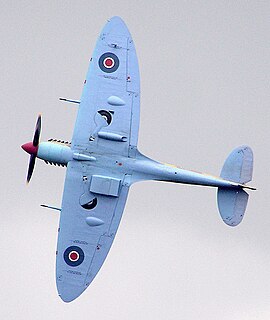
The Handley Page H.P.20 was an experimental monoplane modification of a de Havilland DH.9A, built to study controllable slots and slotted ailerons as high lift devices. It was the first aircraft to fly with controllable slots.

A supersonic airfoil is a cross-section geometry designed to generate lift efficiently at supersonic speeds. The need for such a design arises when an aircraft is required to operate consistently in the supersonic flight regime.

Leading edge Foremost part of a wing or tail surface

The leading edge of an airfoil surface such as a wing is its foremost edge and is therefore the part which first meets the oncoming air.

Villiers XXIV

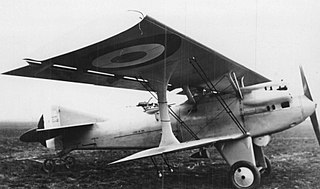
The Villiers XXIV or Villiers 24 CAN2 was a French army night fighter most notable as the first French military aircraft to be fitted with leading edge slats.

References

  1. Kermode, A.C., Mechanics of Flight, Chapter 3
  2. 1 2 3 4 5 Clancy, L.J., Aerodynamics, Section 6.9
  3. Centennial of Flight Archived 2012-10-10 at the Wayback Machine Retrieved 2008-02-19
  4. 1 2 3 4 Aviation Publishers Co. Limited, From the Ground Up, page 26 (27th revised edition) ISBN   0-9690054-9-0
  5. Kermode, A.C., Mechanics of Flight, Figure 3.36
  6. Kermode, A.C., Mechanics of Flight, Figure 3.37
  7. 1 2 Abbott and Von Doenhoff, Theory of Wing Sections, Section 8.6
  8. Crane, Dale: Dictionary of Aeronautical Terms, third edition, page 471. Aviation Supplies & Academics, 1997. ISBN   1-56027-287-2
  9. Kermode, A.C., Mechanics of Flight, Figures 6.6 and 6.7