Pitot-static system

Last updated

A pitot-static system is a system of pressure-sensitive instruments that is most often used in aviation to determine an aircraft's airspeed, Mach number, altitude, and altitude trend. A pitot-static system generally consists of a pitot tube, a static port, and the pitot-static instruments. [1] Other instruments that might be connected are air data computers, flight data recorders, altitude encoders, cabin pressurization controllers, and various airspeed switches. Errors in pitot-static system readings can be extremely dangerous as the information obtained from the pitot static system, such as altitude, is potentially safety-critical. Several commercial airline disasters have been traced to a failure of the pitot-static system. [2]

Contents

Diagram of a pitot-static system including the pitot tube, pitot-static instruments and static port Faa pitot static system.JPG
Diagram of a pitot-static system including the pitot tube, pitot-static instruments and static port

The Code of Federal Regulations (CFRs) require pitot-static systems installed in US-registered aircraft to be tested and inspected every 24 calendar months. [3]

Pitot-static pressure

Examples of pitot tube, static tube, and pitot-static tube. Pitot tube types.svg
Examples of pitot tube, static tube, and pitot-static tube.
Static ports fitted to an Airbus A330 passenger airliner. StaticPort.jpg
Static ports fitted to an Airbus A330 passenger airliner.

The pitot-static system of instruments uses the principle of air pressure gradient. It works by measuring pressures or pressure differences and using these values to assess the speed and altitude. [1] These pressures can be measured either from the static port (static pressure) or the pitot tube (pitot pressure). The static pressure is used in all measurements, while the pitot pressure is used only to determine airspeed.

Pitot pressure

The pitot pressure is obtained from the pitot tube. The pitot pressure is a measure of ram air pressure (the air pressure created by vehicle motion or the air ramming into the tube), which, under ideal conditions, is equal to stagnation pressure, also called total pressure. The pitot tube is most often located on the wing or front section of an aircraft, facing forward, where its opening is exposed to the relative wind. [1] By situating the pitot tube in such a location, the ram air pressure is more accurately measured since it will be less distorted by the aircraft's structure. When airspeed increases, the ram air pressure is increased, which can be translated by the airspeed indicator. [1]

Static pressure

The static pressure is obtained through a static port. The static port is most often a flush-mounted hole on the fuselage of an aircraft, and is located where it can access the air flow in a relatively undisturbed area. [1] Some aircraft may have a single static port, while others may have more than one. In situations where an aircraft has more than one static port, there is usually one located on each side of the fuselage. With this positioning, an average pressure can be taken, which allows for more accurate readings in specific flight situations. [1] An alternative static port may be located inside the cabin of the aircraft as a backup for when the external static port(s) are blocked. A pitot-static tube effectively integrates the static ports into the pitot probe. It incorporates a second coaxial tube (or tubes) with pressure sampling holes on the sides of the probe, outside the direct airflow, to measure the static pressure. When the aircraft climbs, static pressure will decrease.

Multiple pressure

Some pitot-static systems incorporate single probes that contain multiple pressure-transmitting ports that allow for the sensing of air pressure, angle of attack, and angle of sideslip data. Depending on the design, such air data probes may be referred to as 5-hole or 7-hole air data probes. Differential pressure sensing techniques can be used to produce angle of attack and angle of sideslip indications.

Pitot-static instrument

Airspeed indicator diagram showing pressure sources from both the pitot tube and static port ASI-operation-FAA.png
Airspeed indicator diagram showing pressure sources from both the pitot tube and static port

The pitot-static system obtains pressures for interpretation by the pitot-static instruments. While the explanations below explain traditional, mechanical instruments, many modern aircraft use an air data computer (ADC) to calculate airspeed, rate of climb, altitude and Mach number. In some aircraft, two ADCs receive total and static pressure from independent pitot tubes and static ports, and the aircraft's flight data computer compares the information from both computers and checks one against the other. There are also "standby instruments", which are back-up pneumatic instruments employed in the case of problems with the primary instruments.

Airspeed indicator

The airspeed indicator is connected to both the pitot and static pressure sources. The difference between the pitot pressure and the static pressure is called dynamic pressure. The greater the dynamic pressure, the higher the airspeed reported. A traditional mechanical airspeed indicator contains a pressure diaphragm that is connected to the pitot tube. The case around the diaphragm is airtight and is vented to the static port. The higher the speed, the higher the ram pressure, the more pressure exerted on the diaphragm, and the larger the needle movement through the mechanical linkage. [4]

Aneroid Wafer of an altimeter Faa altimeter.JPG
Aneroid Wafer of an altimeter

Altimeter

The pressure altimeter, also known as the barometric altimeter, is used to determine changes in air pressure that occur as the aircraft's altitude changes. [4] Pressure altimeters must be calibrated prior to flight to register the pressure as an altitude above sea level. The instrument case of the altimeter is airtight and has a vent to the static port. Inside the instrument, there is a sealed aneroid barometer. As pressure in the case decreases, the internal barometer expands, which is mechanically translated into a determination of altitude. The reverse is true when descending from higher to lower altitudes. [4]

Machmeter

Aircraft designed to operate at transonic or supersonic speeds will incorporate a machmeter. The machmeter is used to show the ratio of true airspeed in relation to the speed of sound. Most supersonic aircraft are limited as to the maximum Mach number they can fly, which is known as the "Mach limit". The Mach number is displayed on a machmeter as a decimal fraction. [4]

A vertical speed indicator Faa vertical air speed.JPG
A vertical speed indicator

Vertical speed indicator

The variometer, also known as the vertical speed indicator (VSI) or the vertical velocity indicator (VVI), is the pitot-static instrument used to determine whether or not an aircraft is flying in level flight. [5] The vertical speed specifically shows the rate of climb or the rate of descent, which is measured in feet per minute or meters per second. [5] The vertical speed is measured through a mechanical linkage to a diaphragm located within the instrument. The area surrounding the diaphragm is vented to the static port through a calibrated leak (which also may be known as a "restricted diffuser"). [4] When the aircraft begins to increase altitude, the diaphragm will begin to contract at a rate faster than that of the calibrated leak, causing the needle to show a positive vertical speed. The reverse of this situation is true when an aircraft is descending. [4] The calibrated leak varies from model to model, but the average time for the diaphragm to equalize pressure is between 6 and 9 seconds. [4]

Pitot-static errors

There are several situations that can affect the accuracy of the pitot-static instruments. Some of these involve failures of the pitot-static system itself—which may be classified as "system malfunctions"—while others are the result of faulty instrument placement or other environmental factors—which may be classified as "inherent errors". [6]

System malfunctions

Blocked pitot tube

A blocked pitot tube is a pitot-static problem that will only affect airspeed indicators. [6] A blocked pitot tube will cause the airspeed indicator to register an increase in airspeed when the aircraft climbs, even though actual airspeed is constant. (As long as the drain hole is also blocked, as the air pressure would otherwise leak out to the atmosphere.) This is caused by the pressure in the pitot system remaining constant when the atmospheric pressure (and static pressure) are decreasing. Conversely, the airspeed indicator will show a decrease in airspeed when the aircraft descends. The pitot tube is susceptible to becoming clogged by ice, water, insects or some other obstruction. [6] For this reason, aviation regulatory agencies such as the U.S. Federal Aviation Administration (FAA) recommend that the pitot tube be checked for obstructions prior to any flight. [5] To prevent icing, many pitot tubes are equipped with a heating element. A heated pitot tube is required in all aircraft certificated for instrument flight except aircraft certificated as Experimental Amateur-Built. [6]

Blocked static port

A blocked static port is a more serious situation because it affects all pitot-static instruments. [6] One of the most common causes of a blocked static port is airframe icing. A blocked static port will cause the altimeter to freeze at a constant value, the altitude at which the static port became blocked. The vertical speed indicator will read zero and will not change at all, even if vertical speed increases or decreases. The airspeed indicator will reverse the error that occurs with a clogged pitot tube and cause the airspeed to be read less than it actually is as the aircraft climbs. When the aircraft is descending, the airspeed will be over-reported. In most aircraft with unpressurized cabins, an alternative static source is available and can be selected from within the cockpit. [6]

Inherent errors

Inherent errors may fall into several categories, each affecting different instruments. Density errors affect instruments metering airspeed and altitude. This type of error is caused by variations of pressure and temperature in the atmosphere. A compressibility error can arise because the impact pressure will cause the air to compress in the pitot tube. At standard sea level pressure altitude the calibration equation (see calibrated airspeed) correctly accounts for the compression so there is no compressibility error at sea level. At higher altitudes the compression is not correctly accounted for and will cause the instrument to read greater than equivalent airspeed. A correction may be obtained from a chart. Compressibility error becomes significant at altitudes above 10,000 feet (3,000 m) and at airspeeds greater than 200 knots (370 km/h). Hysteresis is an error that is caused by mechanical properties of the aneroid capsules located within the instruments. These capsules, used to determine pressure differences, have physical properties that resist change by retaining a given shape, even though the external forces may have changed. Reversal errors are caused by a false static pressure reading. This false reading may be caused by abnormally large changes in an aircraft's pitch. A large change in pitch will cause a momentary showing of movement in the opposite direction. Reversal errors primarily affect altimeters and vertical speed indicators. [6]

Position errors

Another class of inherent errors is that of position error. A position error is produced by the aircraft's static pressure being different from the air pressure remote from the aircraft. This error is caused by the air flowing past the static port at a speed different from the aircraft's true airspeed. Position errors may provide positive or negative errors, depending on one of several factors. These factors include airspeed, angle of attack, aircraft weight, acceleration, aircraft configuration, and in the case of helicopters, rotor downwash. [6] There are two categories of position errors, which are "fixed errors" and "variable errors". Fixed errors are defined as errors which are specific to a particular model of aircraft. Variable errors are caused by external factors such as deformed panels obstructing the flow of air, or particular situations which may overstress the aircraft. [6]

Lag errors

Lag errors are caused by the fact that any changes in the static or dynamic pressure outside the aircraft require a finite amount of time to make their way down the tubing and affect the gauges. This type of error depends on the length and diameter of the tubing as well as the volume inside the gauges. [7] Lag error is only significant around the time when the airspeed or altitude are changing. It is not a concern for steady level flight.

See also

Related Research Articles

<span class="mw-page-title-main">Pitot tube</span> Device which measures fluid flow velocity, typically around an aircraft or boat

A pitot tube measures fluid flow velocity. It was invented by a French engineer, Henri Pitot, in the early 18th century, and was modified to its modern form in the mid-19th century by a French scientist, Henry Darcy. It is widely used to determine the airspeed of aircraft; the water speed of boats; and the flow velocity of liquids, air, and gases in industry.

<span class="mw-page-title-main">Flight instruments</span> Instruments in an aircrafts cockpit which provide the pilot with crucial information during flight

Flight instruments are the instruments in the cockpit of an aircraft that provide the pilot with data about the flight situation of that aircraft, such as altitude, airspeed, vertical speed, heading and much more other crucial information in flight. They improve safety by allowing the pilot to fly the aircraft in level flight, and make turns, without a reference outside the aircraft such as the horizon. Visual flight rules (VFR) require an airspeed indicator, an altimeter, and a compass or other suitable magnetic direction indicator. Instrument flight rules (IFR) additionally require a gyroscopic pitch-bank, direction and rate of turn indicator, plus a slip-skid indicator, adjustable altimeter, and a clock. Flight into instrument meteorological conditions (IMC) require radio navigation instruments for precise takeoffs and landings.

<span class="mw-page-title-main">Variometer</span> Flight instrument which determines the aircrafts vertical velocity (rate of descent/climb)

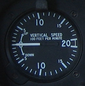
In aviation, a variometer – also known as a rate of climb and descent indicator (RCDI), rate-of-climb indicator, vertical speed indicator (VSI), or vertical velocity indicator (VVI) – is one of the flight instruments in an aircraft used to inform the pilot of the rate of descent or climb. It can be calibrated in metres per second, feet per minute or knots, depending on country and type of aircraft. It is typically connected to the aircraft's external static pressure source.

Aviation is the design, development, production, operation, and use of aircraft, especially heavier-than-air aircraft. Articles related to aviation include:

<span class="mw-page-title-main">Airspeed indicator</span> Flight instrument

The airspeed indicator (ASI) or airspeed gauge is a flight instrument indicating the airspeed of an aircraft in kilometres per hour (km/h), knots (kn), miles per hour (MPH) and/or metres per second (m/s). The recommendation by ICAO is to use km/h, however knots is currently the most used unit. The ASI measures the pressure differential between static pressure from the static port, and total pressure from the pitot tube. This difference in pressure is registered with the ASI pointer on the face of the instrument.

<span class="mw-page-title-main">Aeroperú Flight 603</span> 1996 aviation accident

Aeroperú Flight 603 (PL603/PLI603) was a scheduled passenger flight from Miami International Airport in Miami, Florida, to Arturo Merino Benítez International Airport in Santiago, Chile, with stopovers in Quito, Ecuador, and Lima, Peru. On October 2, 1996, the Boeing 757-23A aircraft flying the final leg of the flight crashed, killing all 70 people aboard.

<span class="mw-page-title-main">Airspeed</span> Speed of an aircraft relative to the surrounding air

In aviation, airspeed is the speed of an aircraft relative to the air. Among the common conventions for qualifying airspeed are:

<span class="mw-page-title-main">True airspeed</span> Speed of an aircraft relative to the air mass through which it is flying

The true airspeed of an aircraft is the speed of the aircraft relative to the air mass through which it is flying. The true airspeed is important information for accurate navigation of an aircraft. Traditionally it is measured using an analogue TAS indicator, but as the Global Positioning System has become available for civilian use, the importance of such air-measuring instruments has decreased. Since indicated, as opposed to true, airspeed is a better indicator of margin above the stall, true airspeed is not used for controlling the aircraft; for these purposes the indicated airspeed – IAS or KIAS – is used. However, since indicated airspeed only shows true speed through the air at standard sea level pressure and temperature, a TAS meter is necessary for navigation purposes at cruising altitude in less dense air. The IAS meter reads very nearly the TAS at lower altitude and at lower speed. On jet airliners the TAS meter is usually hidden at speeds below 200 knots (370 km/h). Neither provides for accurate speed over the ground, since surface winds or winds aloft are not taken into account.

<span class="mw-page-title-main">Indicated airspeed</span>

Indicated airspeed (IAS) is the airspeed of an aircraft as measured by its pitot-static system and displayed by the airspeed indicator (ASI). This is the pilots' primary airspeed reference.

Equivalent airspeed (EAS) is calibrated airspeed (CAS) corrected for the compressibility of air at a non-trivial Mach number. It is also the airspeed at sea level in the International Standard Atmosphere at which the dynamic pressure is the same as the dynamic pressure at the true airspeed (TAS) and altitude at which the aircraft is flying. In low-speed flight, it is the speed which would be shown by an airspeed indicator with zero error. It is useful for predicting aircraft handling, aerodynamic loads, stalling etc.

Calibrated airspeed (CAS) is indicated airspeed corrected for instrument and position error.

Position error is one of the errors affecting the systems in an aircraft for measuring airspeed and altitude. It is not practical or necessary for an aircraft to have an airspeed indicating system and an altitude indicating system that are exactly accurate. A small amount of error is tolerable. It is caused by the location of the static vent that supplies air pressure to the airspeed indicator and altimeter.

<span class="mw-page-title-main">Air data computer</span> Avionics component

An air data computer (ADC) or central air data computer (CADC) computes altitude, vertical speed, air speed, and Mach number from pressure and temperature inputs. It is an essential avionics component found in modern aircraft. This computer, rather than individual instruments, can determine the calibrated airspeed, Mach number, altitude, and altitude trend data from an aircraft's pitot-static system. In some very high speed aircraft such as the Space Shuttle, equivalent airspeed is calculated instead of calibrated airspeed.

<span class="mw-page-title-main">Primary flight display</span> Modern aircraft instrument

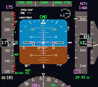
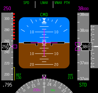
A primary flight display or PFD is a modern aircraft instrument dedicated to flight information. Much like multi-function displays, primary flight displays are built around a Liquid-crystal display or CRT display device. Representations of older six pack or "steam gauge" instruments are combined on one compact display, simplifying pilot workflow and streamlining cockpit layouts.

In fluid mechanics the term static pressure has several uses:

<span class="mw-page-title-main">Birgenair Flight 301</span> Aviation accident in 1996

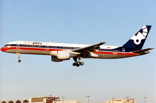
Birgenair Flight 301 was a flight chartered by Turkish-managed Birgenair partner Alas Nacionales from Puerto Plata in the Dominican Republic to Frankfurt, Germany, via Gander, Canada, and Berlin, Germany. On 6 February 1996, the Boeing 757-200 operating the route crashed shortly after take-off from Puerto Plata's Gregorio Luperón International Airport. All 189 people on board died. The cause was pilot error after receiving incorrect airspeed information from one of the pitot tubes, which investigators believe was blocked by a wasp nest built inside it. The aircraft had been sitting unused for 20 days, and without pitot tube covers in place for the preceding 2 days before the crash.

<span class="mw-page-title-main">Machmeter</span> Flight instrument

A Machmeter is an aircraft pitot-static system flight instrument that shows the ratio of the true airspeed to the speed of sound, a dimensionless quantity called Mach number. This is shown on a Machmeter as a decimal fraction. An aircraft flying at the speed of sound is flying at a Mach number of one, expressed as Mach 1.

<span class="mw-page-title-main">Austral Líneas Aéreas Flight 2553</span> 1997 aviation accident

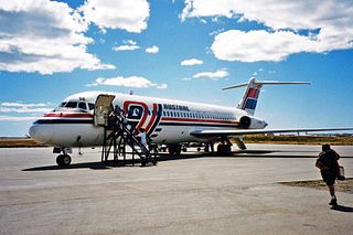
Austral Líneas Aéreas Flight 2553 was an Argentinian domestic scheduled Posadas–Buenos Aires service operated with a McDonnell Douglas DC-9-32 that crashed on the lands of Estancia Magallanes, Nuevo Berlín, 32 kilometres away from Fray Bentos, Uruguay, on 10 October 1997. All 74 passengers and crew died upon impact. The accident remains the deadliest in Uruguayan history.

<span class="mw-page-title-main">Coffin corner (aerodynamics)</span> Dangerous condition in aviation

Coffin corner is the region of flight where a fast but subsonic fixed-wing aircraft's stall speed is near the critical Mach number, at a given gross weight and G-force loading. In this region of flight, it is very difficult to keep an airplane in stable flight. Because the stall speed is the minimum speed required to maintain level flight, any reduction in speed will cause the airplane to stall and lose altitude. Because the critical Mach number is the maximum speed at which air can travel over the wings without losing lift due to flow separation and shock waves, any increase in speed will cause the airplane to lose lift, or to pitch heavily nose-down, and lose altitude.

<span class="mw-page-title-main">Air data boom</span> Aircraft instrument

An air data boom provides air pressure, temperature, and airflow direction data to data acquisition systems for the computation of air, ground, and water vehicle orientation, speed, altitude/depth, and related information. Air data booms can be used as primary sensors or as a "measurement standard" of which primary sensors and instruments are compared to.

References

  1. 1 2 3 4 5 6 Willits, Pat, ed. (2004) [1997]. Guided Flight Discovery - Private Pilot. Abbot, Mike Kailey, Liz. Jeppesen Sanderson. pp. 2–48–2–53. ISBN   0-88487-333-1.
  2. Evans, David (1 May 2004). "Safety: Maintenance Snafu with Static Ports". Avionics Magazine . Retrieved 2017-06-26.
  3. "CFR §91.411 Altimeter system and altitude reporting equipment tests and inspections".
  4. 1 2 3 4 5 6 7 "Pitot-Static Instruments - Level 3 - Pitot-Static Instruments". allstar.fiu.edu. Retrieved 2007-01-07.
  5. 1 2 3 "Pilot Handbook - Chapters 6 through 9" (PDF). FAA. Archived from the original (PDF) on 2007-01-06. Retrieved 2007-01-07.
  6. 1 2 3 4 5 6 7 8 9 "Flight Instruments - Level 3 - Pitot-Static System and Instruments". allstar.fiu.edu. Archived from the original on 2007-01-08. Retrieved 2007-01-07.
  7. Gracey, William. 1981. Measurement of Aircraft Speed and Altitude. New York: John Wiley & Sons. ISBN   0-471-08511-1. p. 8.
  8. "ASN Aircraft accident description Boeing 757-225 TC-GEN — Puerto Plata, Dominican Republic". aviation-safety.net. Retrieved 2007-01-07.
  9. "CVR Database — 2 October 1996 — Aeroperu 603". tailstrike.co. Retrieved 2007-01-07.
  10. "Air Force World: B-2 Crash Cause Identified", AIR FORCE Magazine, July 2008, Vol. 91, No.7, pp. 16–17.
  11. "Training flaws exposed in Rio-Paris crash report". Reuters. 5 July 2012. Retrieved 5 October 2012.