Flight instruments are the instruments in the cockpit of an aircraft that provide the pilot with data about the flight situation of that aircraft, such as altitude, airspeed, vertical speed, heading and much more other crucial information in flight. They improve safety by allowing the pilot to fly the aircraft in level flight, and make turns, without a reference outside the aircraft such as the horizon. Visual flight rules (VFR) require an airspeed indicator, an altimeter, and a compass or other suitable magnetic direction indicator. Instrument flight rules (IFR) additionally require a gyroscopic pitch-bank, direction and rate of turn indicator, plus a slip-skid indicator, adjustable altimeter, and a clock. Flight into instrument meteorological conditions (IMC) require radio navigation instruments for precise takeoffs and landings.

Radio navigation or radionavigation is the application of radio waves to determine a position of an object on the Earth, either the vessel or an obstruction. Like radiolocation, it is a type of radiodetermination.

In aviation, the instrument landing system (ILS) is a precision radio navigation system that provides short-range guidance to aircraft to allow them to approach a runway at night or in bad weather. In its original form, it allows an aircraft to approach until it is 200 feet (61 m) over the ground, within a 1⁄2 mile (800 m) of the runway. At that point the runway should be visible to the pilot; if it is not, they perform a missed approach. Bringing the aircraft this close to the runway dramatically increases the range of weather conditions in which a safe landing can be made. Other versions of the system, or "categories", have further reduced the minimum altitudes, runway visual ranges (RVRs), and transmitter and monitoring configurations designed depending on the normal expected weather patterns and airport safety requirements.

A non-directional beacon (NDB) or non-directional radio beacon is a radio beacon which does not include inherent directional information. Radio beacons are radio transmitters at a known location, used as an aviation or marine navigational aid. NDB are in contrast to directional radio beacons and other navigational aids, such as low-frequency radio range, VHF omnidirectional range (VOR) and tactical air navigation system (TACAN).

An automatic direction finder (ADF) is a marine or aircraft radio-navigation instrument that automatically and continuously displays the relative bearing from the ship or aircraft to a suitable radio station. ADF receivers are normally tuned to aviation or marine NDBs operating in the LW band between 190 – 535 kHz. Like RDF units, most ADF receivers can also receive medium wave (AM) broadcast stations, though these are less reliable for navigational purposes.

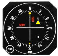
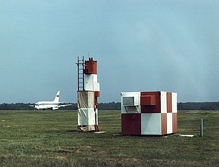
Very High Frequency Omnidirectional Range Station (VOR) is a type of short-range VHF radio navigation system for aircraft, enabling aircraft with a VOR receiver to determine the azimuth, referenced to magnetic north, between the aircraft to/from fixed VOR ground radio beacons. VOR and the first DME(1950) system to provide the slant range distance, were developed in the United States as part of a U.S. civil/military program for Aeronautical Navigation Aids in 1945. Deployment of VOR and DME(1950) began in 1949 by the U.S. CAA. ICAO standardized VOR and DME(1950) in 1950 in ICAO Annex ed.1. Frequencies for the use of VOR are standardized in the very high frequency (VHF) band between 108.00 and 117.95 MHz Chapter 3, Table A. To improve azimuth accuracy of VOR even under difficult siting conditions, Doppler VOR (DVOR) was developed in the 1960s. VOR is according to ICAO rules a primary means navigation system for commercial and general aviation, (D)VOR are gradually decommissioned and replaced by DME-DME RNAV 7.2.3 and satellite based navigation systems such as GPS in the early 21st century. In 2000 there were about 3,000 VOR stations operating around the world, including 1,033 in the US, but by 2013 the number in the US had been reduced to 967. The United States is decommissioning approximately half of its VOR stations and other legacy navigation aids as part of a move to performance-based navigation, while still retaining a "Minimum Operational Network" of VOR stations as a backup to GPS. In 2015, the UK planned to reduce the number of stations from 44 to 19 by 2020.
In aviation, distance measuring equipment (DME) is a radio navigation technology that measures the slant range (distance) between an aircraft and a ground station by timing the propagation delay of radio signals in the frequency band between 960 and 1215 megahertz (MHz). Line-of-visibility between the aircraft and ground station is required. An interrogator (airborne) initiates an exchange by transmitting a pulse pair, on an assigned 'channel', to the transponder ground station. The channel assignment specifies the carrier frequency and the spacing between the pulses. After a known delay, the transponder replies by transmitting a pulse pair on a frequency that is offset from the interrogation frequency by 63 MHz and having specified separation.

The Wide Area Augmentation System (WAAS) is an air navigation aid developed by the Federal Aviation Administration to augment the Global Positioning System (GPS), with the goal of improving its accuracy, integrity, and availability. Essentially, WAAS is intended to enable aircraft to rely on GPS for all phases of flight, including approaches with vertical guidance to any airport within its coverage area. It may be further enhanced with the Local Area Augmentation System (LAAS) also known by the preferred ICAO term Ground-Based Augmentation System (GBAS) in critical areas.

An instrument landing system localizer, or simply localizer, is a system of horizontal guidance in the instrument landing system, which is used to guide aircraft along the axis of the runway.

In aviation, an electronic flight instrument system (EFIS) is a flight instrument display system in an aircraft cockpit that displays flight data electronically rather than electromechanically. An EFIS normally consists of a primary flight display (PFD), multi-function display (MFD), and an engine indicating and crew alerting system (EICAS) display. Early EFIS models used cathode-ray tube (CRT) displays, but liquid crystal displays (LCD) are now more common. The complex electromechanical attitude director indicator (ADI) and horizontal situation indicator (HSI) were the first candidates for replacement by EFIS. Now, however, few flight deck instruments cannot be replaced by an electronic display.

In aviation, an instrument approach or instrument approach procedure (IAP) is a series of predetermined maneuvers for the orderly transfer of an aircraft operating under instrument flight rules from the beginning of the initial approach to a landing, or to a point from which a landing may be made visually. These approaches are approved in the European Union by EASA and the respective country authorities and in the United States by the FAA or the United States Department of Defense for the military. The ICAO defines an instrument approach as "a series of predetermined maneuvers by reference to flight instruments with specific protection from obstacles from the initial approach fix, or where applicable, from the beginning of a defined arrival route to a point from which a landing can be completed and thereafter, if landing is not completed, to a position at which holding or en route obstacle clearance criteria apply."
The microwave landing system (MLS) is an all-weather, precision radio guidance system intended to be installed at large airports to assist aircraft in landing, including 'blind landings'. MLS enables an approaching aircraft to determine when it is aligned with the destination runway and on the correct glidepath for a safe landing. MLS was intended to replace or supplement the instrument landing systems (ILS). MLS has a number of operational advantages over ILS, including a wider selection of channels to avoid interference with nearby installations, excellent performance in all weather, a small "footprint" at the airports, and wide vertical and horizontal "capture" angles that allowed approaches from wider areas around the airport.

A marker beacon is a particular type of VHF radio beacon used in aviation, usually in conjunction with an instrument landing system (ILS), to give pilots a means to determine position along an established route to a destination such as a runway.

A transponder landing system (TLS) is an all-weather, precision landing system that uses existing airborne transponder and instrument landing system (ILS) equipment to create a precision approach at a location where an ILS would normally not be available.

The horizontal situation indicator is an aircraft flight instrument normally mounted below the artificial horizon in place of a conventional heading indicator. It combines a heading indicator with a VHF omnidirectional range-instrument landing system (VOR-ILS) display.
The difference in the depth of modulation (DDM) is used by instrument landing systems in conjunction with the associated airborne receiving equipment to define a position in airspace. DDM is usually expressed in percentage but may also be expressed in microamperes. The two individual audio modulation frequencies and their associated sidebands are 90 and 150 Hz. The DDM for a localizer at the outer extremity of the course sector is 15.5% or an electric current equivalent of 150 microamperes full scale deflection.
Space modulation is a radio amplitude modulation technique used in instrument landing systems (ILS) that incorporates the use of multiple antennas fed with various radio frequency powers and phases to create different depths of modulation within various volumes of three-dimensional airspace. This modulation method differs from internal modulation methods inside most other radio transmitters in that the phases and powers of the two individual signals mix within airspace, rather than in a modulator.
L-Tronics was a company based in Santa Barbara, California that specialized in the design and manufacture of direction finding (DF) equipment for search and rescue applications, used to locate signals originating from emergency locator beacons. These include Emergency Locator Transmitters (ELTs) used by aircraft, Emergency Position Indicator Radio Beacons (EPIRBs) used by marine vehicles, and Personal Locator Beacons (PLBs). One major operator of L-Tronics devices is the Civil Air Patrol.

Alitalia Flight 404 (AZ404/AZA404) was an international passenger flight scheduled to fly from Linate Airport in Milan, Italy, to Zürich Airport in Zürich, Switzerland, which crashed on 14 November 1990. The McDonnell Douglas DC-9-32, operated by Alitalia, crashed into the woodlands of Weiach as it approached Zurich Airport, killing all 46 occupants on board.

The low-frequency radio range, also known as the four-course radio range, LF/MF four-course radio range, A-N radio range, Adcock radio range, or commonly "the range", was the main navigation system used by aircraft for instrument flying in the 1930s and 1940s, until the advent of the VHF omnidirectional range (VOR), beginning in the late 1940s. It was used for en route navigation as well as instrument approaches and holds.