Wing fence

Last updated
Felixstowe F.2A during an anti-submarine patrol flight in the Great war Felixstowe F.2A - RNAS 1914-1918 Q27501.jpg
Felixstowe F.2A during an anti-submarine patrol flight in the Great war
Three wing fences are installed on the wing of a Tu-95 Vypolnenie planovykh poletov na aviabaze <<Kipelovo>> (4).jpg
Three wing fences are installed on the wing of a Tu-95
The MiG-17 included prominent wing fences MiG-17F Top View.JPG
The MiG-17 included prominent wing fences
Close up of the wing fences of a Sukhoi Su-22. This plane was used by Former East German Air Force and retired after German unification. Wing fence sukhoi-22m-4.jpg
Close up of the wing fences of a Sukhoi Su-22. This plane was used by Former East German Air Force and retired after German unification.

Wing fences, also known as boundary layer fences and potential fences are fixed aerodynamic devices attached to aircraft wings. Often seen on swept-wing aircraft, wing fences are flat plates fixed to the upper surfaces parallel to the wing chord and in line with the free stream airflow, typically wrapping around the leading edge. By obstructing span-wise airflow along the wing, they prevent the entire wing from stalling at once, as opposed to wingtip devices, which increase aerodynamic efficiency by seeking to recover wing vortex energy.

Contents

As a swept-wing aircraft slows toward the stall speed of the wing, the angle of the leading edge forces some of the airflow sidewise, toward the wing tip. This process is progressive: airflow near the middle of the wing is affected not only by the leading edge angle, but also the spanwise airflow from the wing root. At the wing tip the airflow can end up being almost all spanwise, as opposed to front-to-back over the wing, meaning that the effective airspeed drops well below the stall. Because the geometry of swept wings typically places the wingtips of an aircraft aft of its center of gravity, lift generated at the wingtips tends to create a nose-down pitching moment. When the wingtips stall, both the lift and the associated nose-down pitching moment rapidly diminish. The loss of the nose-down pitching moment leaves the previously balanced aircraft with a net nose-up pitching moment. This forces the nose of the aircraft up, increasing the angle of attack and leading to stall over a greater portion of the wing. The result is a rapid and powerful pitch-up followed by a complete stall, a difficult situation for a pilot to recover from. [1] The "Sabre dance" (which caused many F-100 Super Sabres to crash) is a notable example of this behavior.

Wing fences delay, or eliminate, these effects by preventing the spanwise flow from moving too far along the wing and gaining speed. When meeting the fence, the air is directed back over the wing surface. Similar solutions included a notch or dogtooth in the leading edge, as seen on the Avro Arrow, or the use of slats, as on the earlier versions of the F-86. Slats can act as fences directly, in the form of their actuators, but also reduce the problem by improving the angle of attack response of the wing and moving the stall point to a lower speed. [1]
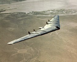
Northrop YB-49 Flying wing, a heavy bomber prototype. First flight in 1947 YB49-2 300.jpg
Northrop YB-49 Flying wing, a heavy bomber prototype. First flight in 1947

Although wing fences over the wing have been known in the UK since 1914, probably due to the RAF's spin research program begun as early as 1912, the invention of the fences is often attributed to German aerodynamicist Liebe of Messerschmitt, with a patent application in 1938. [2]

By 1947, after the introduction of subsonic swept wings, fences independently implemented in the USSR and the US: Lavochkin La-160, Mikoyan MiG-15, Northrop YB-49, McDonnell XF-85. But in the USSR such fences were used more often and for the longest time, they were made large and numerous: from MiG-15 to MiG-25, from Tu-128 to Tu-160, from Su-7 to Su-22.

See also

Related Research Articles

<span class="mw-page-title-main">Wing</span> Appendage used for flight

A wing is a type of fin that produces both lift and drag while moving through air. Wings are defined by two shape characteristics, an airfoil section and a planform. Wing efficiency is expressed as lift-to-drag ratio, which compares the benefit of lift with the air resistance of a given wing shape, as it flies. Aerodynamics is the study of wing performance in air.

<span class="mw-page-title-main">Stall (fluid dynamics)</span> Abrupt reduction in lift due to flow separation

In fluid dynamics, a stall is a reduction in the lift coefficient generated by a foil as angle of attack exceeds its critical value. The critical angle of attack is typically about 15°, but it may vary significantly depending on the fluid, foil – including its shape, size, and finish – and Reynolds number.

<span class="mw-page-title-main">Delta wing</span> Triangle shaped aircraft wing configuration

A delta wing is a wing shaped in the form of a triangle. It is named for its similarity in shape to the Greek uppercase letter delta (Δ).

<span class="mw-page-title-main">Leading-edge extension</span> Anti-stall control surface on aircraft

A leading-edge extension (LEX) is a small extension to an aircraft wing surface, forward of the leading edge. The primary reason for adding an extension is to improve the airflow at high angles of attack and low airspeeds, to improve handling and delay the stall. A dog tooth can also improve airflow and reduce drag at higher speeds.

<span class="mw-page-title-main">Vortex generator</span> Aerodynamic device

A vortex generator (VG) is an aerodynamic device, consisting of a small vane usually attached to a lifting surface or a rotor blade of a wind turbine. VGs may also be attached to some part of an aerodynamic vehicle such as an aircraft fuselage or a car. When the airfoil or the body is in motion relative to the air, the VG creates a vortex, which, by removing some part of the slow-moving boundary layer in contact with the airfoil surface, delays local flow separation and aerodynamic stalling, thereby improving the effectiveness of wings and control surfaces, such as flaps, elevators, ailerons, and rudders.

<span class="mw-page-title-main">Swept wing</span> Plane wing that angles backwards or forwards

A swept wing is a wing angled either backward or occasionally forward from its root rather than perpendicular to the fuselage.

<span class="mw-page-title-main">Wingtip device</span> Aircraft component fixed to the end of the wings to improve performance

Wingtip devices are intended to improve the efficiency of fixed-wing aircraft by reducing drag. Although there are several types of wing tip devices which function in different manners, their intended effect is always to reduce an aircraft's drag. Wingtip devices can also improve aircraft handling characteristics and enhance safety for following aircraft. Such devices increase the effective aspect ratio of a wing without greatly increasing the wingspan. Extending the span would lower lift-induced drag, but would increase parasitic drag and would require boosting the strength and weight of the wing. At some point, there is no net benefit from further increased span. There may also be operational considerations that limit the allowable wingspan.

<span class="mw-page-title-main">Flight control surfaces</span> Surface that allows a pilot to adjust and control an aircrafts flight attitude

Aircraft flight control surfaces are aerodynamic devices allowing a pilot to adjust and control the aircraft's flight attitude.

<span class="mw-page-title-main">High-lift device</span> Wing surface area adjuster, typically for shortening take-off and landing

In aircraft design and aerospace engineering, a high-lift device is a component or mechanism on an aircraft's wing that increases the amount of lift produced by the wing. The device may be a fixed component, or a movable mechanism which is deployed when required. Common movable high-lift devices include wing flaps and slats. Fixed devices include leading-edge slots, leading edge root extensions, and boundary layer control systems.

<span class="mw-page-title-main">Flap (aeronautics)</span> Anti-stalling high-lift device on aircraft

A flap is a high-lift device used to reduce the stalling speed of an aircraft wing at a given weight. Flaps are usually mounted on the wing trailing edges of a fixed-wing aircraft. Flaps are used to reduce the take-off distance and the landing distance. Flaps also cause an increase in drag so they are retracted when not needed.

<span class="mw-page-title-main">Leading-edge cuff</span> Fixed aerodynamic wing device

A leading-edge cuff is a fixed aerodynamic wing device employed on fixed-wing aircraft to improve the stall and spin characteristics. Cuffs may be either factory-designed or an after-market add-on modification.

<span class="mw-page-title-main">Leading-edge slot</span> Anti-stall control surface on aircraft

A leading-edge slot is a fixed aerodynamic feature of the wing of some aircraft to reduce the stall speed and promote good low-speed handling qualities. A leading-edge slot is a spanwise gap in each wing, allowing air to flow from below the wing to its upper surface. In this manner they allow flight at higher angles of attack and thus reduce the stall speed.

<span class="mw-page-title-main">Vortex lift</span> Lift from highly sweptback aircraft wings

Vortex lift is that portion of lift due to the action of leading edge vortices. It is generated by wings with highly sweptback, sharp, leading edges or highly-swept wing-root extensions added to a wing of moderate sweep. It is sometimes known as non-linear lift due to its rapid increase with angle of attack and controlled separation lift, to distinguish it from conventional lift which occurs with attached flow.

<span class="mw-page-title-main">Pitch-up</span>

In aerodynamics, pitch-up is an uncommanded nose-upwards rotation of an aircraft. It is an undesirable characteristic that has been observed mostly in experimental swept-wing aircraft at high subsonic Mach numbers or high angle of attack.

<span class="mw-page-title-main">Washout (aeronautics)</span> Characteristic of aircraft wing design

Washout is a characteristic of aircraft wing design which deliberately reduces the lift distribution across the span of an aircraft’s wing. The wing is designed so that the angle of incidence is greater at the wing roots and decreases across the span, becoming lowest at the wing tip. This is usually to ensure that at stall speed the wing root stalls before the wing tips, providing the aircraft with continued aileron control and some resistance to spinning. Washout may also be used to modify the spanwise lift distribution to reduce lift-induced drag.

Supermaneuverability is the capability of fighter aircraft to execute tactical maneuvers that are not possible with purely aerodynamic techniques. Such maneuvers can involve controlled side-slipping or angles of attack beyond maximum lift.

<span class="mw-page-title-main">Wing configuration</span> Describes the general shape and layout of an aircraft wing

The wing configuration or planform of a fixed-wing aircraft is its arrangement of lifting and related surfaces.

<span class="mw-page-title-main">Vortilon</span> Aerodynamic device

Vortilons are fixed aerodynamic devices on aircraft wings used to improve handling at low speeds.

<span class="mw-page-title-main">Crescent wing</span> Aircraft wing configuration

The crescent wing is a fixed-wing aircraft configuration in which a swept wing has a greater sweep angle on the inboard section than the outboard, giving the wing a crescent shape.

<span class="mw-page-title-main">Leading-edge droop flap</span> Aerodynamic device

The leading-edge droop flap is a device on the leading edge of aircraft wings designed to improve airflow at high angles of attack. The droop flap is similar to the leading-edge slat and the Krueger flap, but with the difference that the entire leading edge section rotates downwards, whereas the slat and Krueger flap are panels which move away from the wing leading edge when it is deployed.

References

  1. 1 2 Hurt, H. H. Jr., "NAVAIR 00-80T-80, Aerodynamics for Naval Aviators". Naval Air Systems Command, 1965, p. 86. at faa.gov
  2. (in German) DE 700625 "Vorrichtung zum Verhindern der Ausbreitung von Strömungsstörungen an Flugzeugflügeln" filed on September 27, 1938.