Ripple (electrical)

Last updated

Ripple (specifically ripple voltage) in electronics is the residual periodic variation of the DC voltage within a power supply which has been derived from an alternating current (AC) source. This ripple is due to incomplete suppression of the alternating waveform after rectification. Ripple voltage originates as the output of a rectifier or from generation and commutation of DC power.

Contents

Ripple (specifically ripple current or surge current) may also refer to the pulsed current consumption of non-linear devices like capacitor-input rectifiers.

As well as these time-varying phenomena, there is a frequency domain ripple that arises in some classes of filter and other signal processing networks. In this case the periodic variation is a variation in the insertion loss of the network against increasing frequency. The variation may not be strictly linearly periodic. In this meaning also, ripple is usually to be considered an incidental effect, its existence being a compromise between the amount of ripple and other design parameters.

Ripple is wasted power, and has many undesirable effects in a DC circuit: it heats components, causes noise and distortion, and may cause digital circuits to operate improperly. Ripple may be reduced by an electronic filter, and eliminated by a voltage regulator.

Voltage ripple

A non-ideal DC voltage waveform can be viewed as a composite of a constant DC component (offset) with an alternating (AC) voltage—the ripple voltage—overlaid. The ripple component is often small in magnitude relative to the DC component, but in absolute terms, ripple (as in the case of HVDC transmission systems) may be thousands of volts. Ripple itself is a composite (non-sinusoidal) waveform consisting of harmonics of some fundamental frequency which is usually the original AC line frequency, but in the case of switched-mode power supplies, the fundamental frequency can be tens of kilohertz to megahertz. The characteristics and components of ripple depend on its source: there is single-phase half- and full-wave rectification, and three-phase half- and full-wave rectification. Rectification can be controlled (uses Silicon Controlled Rectifiers (SCRs)) or uncontrolled (uses diodes). There is in addition, active rectification which uses transistors.

Various properties of ripple voltage may be important depending on application: the equation of the ripple for Fourier analysis to determine the constituent harmonics; the peak (usually peak-to-peak) value of the voltage; the root mean square (RMS) value of the voltage which is a component of power transmitted; the ripple factor γ, the ratio of RMS value to DC voltage output; the conversion ratio (also called the rectification ratio or "efficiency") η, the ratio of DC output power to AC input power; and form-factor, the ratio of the RMS value of the output voltage to the average value of the output voltage. Analogous ratios for output ripple current may also be computed.

An electronic filter with high impedance at the ripple frequency may be used to reduce ripple voltage and increase or decrease DC output; such a filter is often called a smoothing filter.

The initial step in AC to DC conversion is to send the AC current through a rectifier. The ripple voltage output is very large in this situation; the peak-to-peak ripple voltage is equal to the peak AC voltage minus the forward voltage of the rectifier diodes. In the case of an SS silicon diode, the forward voltage is 0.7 V; for vacuum tube rectifiers, forward voltage usually ranges between 25 and 67 V (5R4). The output voltage is a sine wave with the negative half-cycles inverted. The equation is:

The Fourier expansion of the function is:

Several relevant properties are apparent on inspection of the Fourier series:

The output voltages are:

where

  • is the time-varying voltage across the load, for period 0 to T
  • is the period of , may be taken as radians

The ripple factor is:

The form factor is:

The peak factor is:

The conversion ratio is:

The transformer utilization factor is:

Filtering

Full-wave center-tapped rectifier with capacitor filter Rectifier with reservoir.svg
Full-wave center-tapped rectifier with capacitor filter

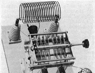
Reducing ripple is only one of several principal considerations in power supply filter design. [nb 1] The filtering of ripple voltage is analogous to filtering other kinds of signals. However, in AC/DC power conversion as well as DC power generation, high voltages and currents or both may be output as ripple. Therefore, large discrete components like high ripple-current rated electrolytic capacitors, large iron-core chokes and wire-wound power resistors are best suited to reduce ripple to manageable proportions before passing the current to an IC component like a voltage regulator, or on to the load. The kind of filtering required depends on the amplitude of the various harmonics of the ripple and the demands of the load. For example, a moving coil (MC) input circuit of a phono preamplifier may require that ripple be reduced to no more than a few hundred nanovolts (10−9V). In contrast, a battery charger, being a wholly resistive circuit, does not require any ripple filtering. Since the desired output is direct current (essentially 0 Hz), ripple filters are usually configured as low pass filters characterized by shunt capacitors and series chokes. Series resistors may replace chokes for reducing the output DC voltage, and shunt resistors may be used for voltage regulation.

Filtering in power supplies

Most power supplies are now switched mode designs. The filtering requirements for such power supplies are much easier to meet owing to the high frequency of the ripple waveform. The ripple frequency in switch-mode power supplies is not related to the line frequency, but is instead a multiple of the frequency of the chopper circuit, which is usually in the range of 50 kHz to 1 MHz.[ citation needed ]

Capacitor vs choke input filters

A capacitor input filter (in which the first component is a shunt capacitor) and choke input filter (which has a series choke as the first component) can both reduce ripple, but have opposing effects on voltage and current, and the choice between them depends on the characteristics of the load. Capacitor input filters have poor voltage regulation, so are preferred for use in circuits with stable loads and low currents (because low currents reduce ripple here). Choke input filters are preferred for circuits with variable loads and high currents (since a choke outputs a stable voltage and higher current means less ripple in this case).

The number of reactive components in a filter is called its order. Each reactive component reduces signal strength by 6 dB/octave above (or below for a high-pass filter) the corner frequency of the filter, so that a 2nd-order low-pass filter for example, reduces signal strength by 12 dB/octave above the corner frequency. Resistive components (including resistors and parasitic elements like the DCR of chokes and ESR of capacitors) also reduce signal strength, but their effect is linear, and does not vary with frequency.

A common arrangement is to allow the rectifier to work into a large smoothing capacitor which acts as a reservoir. After a peak in output voltage the capacitor supplies the current to the load and continues to do so until the capacitor voltage has fallen to the value of the now rising next half-cycle of rectified voltage. At that point the rectifier conducts again and delivers current to the reservoir until peak voltage is again reached.

As a function of load resistance

If the RC time constant is large in comparison to the period of the AC waveform, then a reasonably accurate approximation can be made by assuming that the capacitor voltage falls linearly. A further useful assumption can be made if the ripple is small compared to the DC voltage. In this case the phase angle through which the rectifier conducts will be small and it can be assumed that the capacitor is discharging all the way from one peak to the next with little loss of accuracy. [1]

Ripple voltage from a full-wave rectifier, before and after the application of a smoothing capacitor Smoothed ripple gray background.svg
Ripple voltage from a full-wave rectifier, before and after the application of a smoothing capacitor

With the above assumptions the peak-to-peak ripple voltage can be calculated as:

The definition of capacitance and current are [2]

where is the amount of charge. The current and time is taken from start of capacitor discharge until the minimum voltage on a full wave rectified signal as shown on the figure to the right. The time would then be equal to half the period of the full wave input.

Combining the three equations above to determine gives,

Thus, for a full-wave rectifier: [3]

where

  • is the peak-to-peak ripple voltage
  • is the current in the circuit
  • is the source (line) frequency of the AC power
  • is the capacitance

For the RMS value of the ripple voltage, the calculation is more involved as the shape of the ripple waveform has a bearing on the result. Assuming a sawtooth waveform is a similar assumption to the ones above. The RMS value of a sawtooth wave is where is peak voltage. With the further approximation that is , it yields the result: [4]

where

where

  • is the ripple factor
  • is the resistance of the load
  • For the approximated formula, it is assumed that XCR; this is a little larger than the actual value because a sawtooth wave comprises odd harmonics that aren't present in the rectified voltage.

As a function of series choke

Another approach to reducing ripple is to use a series choke. A choke has a filtering action[ clarification needed ] and consequently produces a smoother waveform with fewer high-order harmonics. Against this, the DC output is close to the average input voltage as opposed to the voltage with the reservoir capacitor which is close to the peak input voltage. Starting with the Fourier term for the second harmonic, and ignoring higher-order harmonics,

the ripple factor is given by: [5]

For

This is a little less than 0.483 because higher-order harmonics were omitted from consideration. (See Inductance.)

There is a minimum inductance (which is relative to the resistance of the load) required in order for a series choke to continuously conduct current. If the inductance falls below that value, current will be intermittent and output DC voltage will rise from the average input voltage to the peak input voltage; in effect, the inductor will behave like a capacitor. That minimum inductance, called the critical inductance is where R is the load resistance and f the line frequency. This gives values of L = R/1131 (often stated as R/1130) for 60 Hz mains rectification, and L = R/942 for 50 Hz mains rectification. Additionally, interrupting current to an inductor will cause its magnetic flux to collapse exponentially; as current falls, a voltage spike composed of very high harmonics results which can damage other components of the power supply or circuit. This phenomenon is called flyback voltage.

The complex impedance of a series choke is effectively part of the load impedance, so that lightly loaded circuits have increased ripple (just the opposite of a capacitor input filter). For that reason, a choke input filter is almost always part of an LC filter section, whose ripple reduction is independent of load current. The ripple factor is:

where

In high voltage/low current circuits, a resistor may replace the series choke in an LC filter section (creating an RC filter section). This has the effect of reducing the DC output as well as ripple. The ripple factor is

if RL >> R, which makes an RC filter section practically independent of load

where

  • is the resistance of the filter resistor

Similarly because of the independence of LC filter sections with respect to load, a reservoir capacitor is also commonly followed by one resulting in a low-pass Π-filter. [6] A Π-filter results in a much lower ripple factor than a capacitor or choke input filter alone. It may be followed by additional LC or RC filter sections to further reduce ripple to a level tolerable by the load. However, use of chokes is deprecated in contemporary designs for economic reasons.

Voltage regulation

A more common solution where good ripple rejection is required is to use a reservoir capacitor to reduce the ripple to something manageable and then pass the current through a voltage regulator circuit. The regulator circuit, as well as providing a stable output voltage, will incidentally filter out nearly all of the ripple as long as the minimum level of the ripple waveform does not go below the voltage being regulated to. [7] Switched-mode power supplies usually include a voltage regulator as part of the circuit.

Voltage regulation is based on a different principle than filtering: it relies on the peak inverse voltage of a diode or series of diodes to set a maximum output voltage; it may also use one or more voltage amplification devices like transistors to boost voltage during sags. Because of the non-linear characteristics of these devices, the output of a regulator is free of ripple. A simple voltage regulator may be made with a series resistor to drop voltage followed by a shunt zener diode whose Peak Inverse Voltage (PIV) sets the maximum output voltage; if voltage rises, the diode shunts away current to maintain regulation.

Effects of ripple

Ripple is undesirable in many electronic applications for a variety of reasons:

Ripple current

Ripple current is a periodic non-sinusoidal waveform derived from an AC power source characterized by high amplitude narrow bandwidth pulses. The pulses coincide with peak or near peak amplitude of an accompanying sinusoidal voltage waveform.

Ripple current results in increased dissipation in parasitic resistive portions of circuits like ESR of capacitors, DCR of transformers and inductors, internal resistance of storage batteries. The dissipation is proportional to the current squared times resistance (I2R). The RMS value of ripple current can be many times the RMS of the load current.

Frequency-domain ripple

Ripple on a fifth-order prototype Chebyshev filter Tchebyscheff5.png
Ripple on a fifth-order prototype Chebyshev filter

Ripple in the context of the frequency domain refers to the periodic variation in insertion loss with frequency of a filter or some other two-port network. Not all filters exhibit ripple, some have monotonically increasing insertion loss with frequency such as the Butterworth filter. Common classes of filter which exhibit ripple are the Chebyshev filter, inverse Chebyshev filter and the Elliptical filter. [9] The ripple is not usually strictly linearly periodic as can be seen from the example plot. Other examples of networks exhibiting ripple are impedance matching networks that have been designed using Chebyshev polynomials. The ripple of these networks, unlike regular filters, will never reach 0 dB at minimum loss if designed for optimum transmission across the passband as a whole. [10]

The amount of ripple can be traded for other parameters in the filter design. For instance, the rate of roll-off from the passband to the stopband can be increased at the expense of increasing the ripple without increasing the order of the filter (that is, the number of components has stayed the same). On the other hand, the ripple can be reduced by increasing the order of the filter while at the same time maintaining the same rate of roll-off. [10]

See also

Notes

  1. Power supply output requirements usually specify a minimum DC voltage, an output voltage range or percentage of voltage regulation, ripple factor. The filter must also take into account the load impedance, source voltage and voltage regulation, and power factor (i.e. for a transformer), line voltage variation, and any necessary filtering of source noise or harmonic distortion.

Related Research Articles

<span class="mw-page-title-main">Inductor</span> Passive two-terminal electrical component that stores energy in its magnetic field

An inductor, also called a coil, choke, or reactor, is a passive two-terminal electrical component that stores energy in a magnetic field when electric current flows through it. An inductor typically consists of an insulated wire wound into a coil.

The total harmonic distortion is a measurement of the harmonic distortion present in a signal and is defined as the ratio of the sum of the powers of all harmonic components to the power of the fundamental frequency. Distortion factor, a closely related term, is sometimes used as a synonym.

<span class="mw-page-title-main">Electrical impedance</span> Opposition of a circuit to a current when a voltage is applied

In electrical engineering, impedance is the opposition to alternating current presented by the combined effect of resistance and reactance in a circuit.

<span class="mw-page-title-main">Rectifier</span> Electrical device that converts AC to DC

A rectifier is an electrical device that converts alternating current (AC), which periodically reverses direction, to direct current (DC), which flows in only one direction. The reverse operation is performed by an inverter.

A resistor–capacitor circuit, or RC filter or RC network, is an electric circuit composed of resistors and capacitors. It may be driven by a voltage or current source and these will produce different responses. A first order RC circuit is composed of one resistor and one capacitor and is the simplest type of RC circuit.

Chebyshev filters are analog or digital filters that have a steeper roll-off than Butterworth filters, and have either passband ripple or stopband ripple. Chebyshev filters have the property that they minimize the error between the idealized and the actual filter characteristic over the range of the filter, but with ripples in the passband. This type of filter is named after Pafnuty Chebyshev because its mathematical characteristics are derived from Chebyshev polynomials. Type I Chebyshev filters are usually referred to as "Chebyshev filters", while type II filters are usually called "inverse Chebyshev filters".

<span class="mw-page-title-main">Voltage divider</span> Linear circuit that produces an output voltage that is a fraction of its input voltage

In electronics, a voltage divider (also known as a potential divider) is a passive linear circuit that produces an output voltage (Vout) that is a fraction of its input voltage (Vin). Voltage division is the result of distributing the input voltage among the components of the divider. A simple example of a voltage divider is two resistors connected in series, with the input voltage applied across the resistor pair and the output voltage emerging from the connection between them.

<span class="mw-page-title-main">Josephson effect</span> Quantum physical phenomenon

In physics, the Josephson effect is a phenomenon that occurs when two superconductors are placed in proximity, with some barrier or restriction between them. It is an example of a macroscopic quantum phenomenon, where the effects of quantum mechanics are observable at ordinary, rather than atomic, scale. The Josephson effect has many practical applications because it exhibits a precise relationship between different physics quantities, such as voltage and frequency, facilitating highly accurate measurements.

<span class="mw-page-title-main">Butterworth filter</span> Type of signal processing filter

The Butterworth filter is a type of signal processing filter designed to have a frequency response that is as flat as possible in the passband. It is also referred to as a maximally flat magnitude filter. It was first described in 1930 by the British engineer and physicist Stephen Butterworth in his paper entitled "On the Theory of Filter Amplifiers".

<span class="mw-page-title-main">LC circuit</span> Electrical "resonator" circuit, consisting of inductive and capacitive elements with no resistance

An LC circuit, also called a resonant circuit, tank circuit, or tuned circuit, is an electric circuit consisting of an inductor, represented by the letter L, and a capacitor, represented by the letter C, connected together. The circuit can act as an electrical resonator, an electrical analogue of a tuning fork, storing energy oscillating at the circuit's resonant frequency.

<span class="mw-page-title-main">Mathematics of three-phase electric power</span> Mathematics and basic principles of three-phase electric power

In electrical engineering, three-phase electric power systems have at least three conductors carrying alternating voltages that are offset in time by one-third of the period. A three-phase system may be arranged in delta (∆) or star (Y). A wye system allows the use of two different voltages from all three phases, such as a 230/400 V system which provides 230 V between the neutral and any one of the phases, and 400 V across any two phases. A delta system arrangement only provides one voltage, but it has a greater redundancy as it may continue to operate normally with one of the three supply windings offline, albeit at 57.7% of total capacity. Harmonic current in the neutral may become very large if nonlinear loads are connected.

<span class="mw-page-title-main">Phasor</span> Complex number representing a particular sine wave

In physics and engineering, a phasor is a complex number representing a sinusoidal function whose amplitude, angular frequency, and initial phase are time-invariant. It is related to a more general concept called analytic representation, which decomposes a sinusoid into the product of a complex constant and a factor depending on time and frequency. The complex constant, which depends on amplitude and phase, is known as a phasor, or complex amplitude, and sinor or even complexor.

A resistor–inductor circuit, or RL filter or RL network, is an electric circuit composed of resistors and inductors driven by a voltage or current source. A first-order RL circuit is composed of one resistor and one inductor, either in series driven by a voltage source or in parallel driven by a current source. It is one of the simplest analogue infinite impulse response electronic filters.

<span class="mw-page-title-main">AC power</span> Power in alternating current systems

In an electric circuit, instantaneous power is the time rate of flow of energy past a given point of the circuit. In alternating current circuits, energy storage elements such as inductors and capacitors may result in periodic reversals of the direction of energy flow. Its SI unit is the watt.

<span class="mw-page-title-main">Buck converter</span> DC-DC voltage step-down power converter

A buck converter or step-down converter is a DC-to-DC converter which steps down voltage from its input (supply) to its output (load). It is a class of switched-mode power supply. Switching converters provide much greater power efficiency as DC-to-DC converters than linear regulators, which are simpler circuits that lower voltages by dissipating power as heat, but do not step up output current. The efficiency of buck converters can be very high, often over 90%, making them useful for tasks such as converting a computer's main supply voltage, which is usually 12 V, down to lower voltages needed by USB, DRAM and the CPU, which are usually 5, 3.3 or 1.8 V.

<span class="mw-page-title-main">Electrical resonance</span>

Electrical resonance occurs in an electric circuit at a particular resonant frequency when the impedances or admittances of circuit elements cancel each other. In some circuits, this happens when the impedance between the input and output of the circuit is almost zero and the transfer function is close to one.

In an electric power transmission system, a thyristor-controlled reactor (TCR) is a reactance connected in series with a bidirectional thyristor valve. The thyristor valve is phase-controlled, which allows the value of delivered reactive power to be adjusted to meet varying system conditions. Thyristor-controlled reactors can be used for limiting voltage rises on lightly loaded transmission lines. Another device which used to be used for this purpose is a magnetically controlled reactor (MCR), a type of magnetic amplifier otherwise known as a transductor.

<span class="mw-page-title-main">RLC circuit</span> Resistor Inductor Capacitor Circuit

An RLC circuit is an electrical circuit consisting of a resistor (R), an inductor (L), and a capacitor (C), connected in series or in parallel. The name of the circuit is derived from the letters that are used to denote the constituent components of this circuit, where the sequence of the components may vary from RLC.

<span class="mw-page-title-main">Transimpedance amplifier</span> Amplifier that converts current to voltage

In electronics, a transimpedance amplifier (TIA) is a current to voltage converter, almost exclusively implemented with one or more operational amplifiers. The TIA can be used to amplify the current output of Geiger–Müller tubes, photo multiplier tubes, accelerometers, photo detectors and other types of sensors to a usable voltage. Current to voltage converters are used with sensors that have a current response that is more linear than the voltage response. This is the case with photodiodes where it is not uncommon for the current response to have better than 1% nonlinearity over a wide range of light input. The transimpedance amplifier presents a low impedance to the photodiode and isolates it from the output voltage of the operational amplifier. In its simplest form a transimpedance amplifier has just a large valued feedback resistor, Rf. The gain of the amplifier is set by this resistor and because the amplifier is in an inverting configuration, has a value of -Rf. There are several different configurations of transimpedance amplifiers, each suited to a particular application. The one factor they all have in common is the requirement to convert the low-level current of a sensor to a voltage. The gain, bandwidth, as well as current and voltage offsets change with different types of sensors, requiring different configurations of transimpedance amplifiers.

<span class="mw-page-title-main">Capacitive power supply</span>

A capacitive power supply, also called a capacitive dropper, is a type of power supply that uses the capacitive reactance of a capacitor to reduce higher AC mains voltage to a lower DC voltage.

References

  1. Ryder, pp 107–115
  2. "Capacitor Input Filter : Part3". www.yourelectrichome.com. Retrieved 2018-09-25.
  3. Millman–Halkias, pp 112–114
  4. Ryder, p 113
  5. Ryder, pp 115117
  6. Ryder pp 117123
  7. Ryder pp 353355
  8. Wharton, W & Howorth, D, Principles of Television Reception, p70, Pitman Publishing, 1971
  9. Matthaei et al., pp 8595
  10. 1 2 Matthaei et al., pp 120135