Equivalent series resistance

Last updated

Capacitors and inductors as used in electric circuits are not ideal components with only capacitance or inductance. However, they can be treated, to a very good degree of approximation, as being ideal capacitors and inductors in series with a resistance; this resistance is defined as the equivalent series resistance (ESR). If not otherwise specified, the ESR is always an AC resistance, which means it is measured at specified frequencies, 100 kHz for switched-mode power supply components, 120 Hz for linear power-supply components, and at its self-resonant frequency for general-application components. Additionally, audio components may report a "Q factor", incorporating ESR among other things, at 1000 Hz.

Contents

Overview

Electrical circuit theory deals with ideal resistors, capacitors and inductors, each assumed to contribute only resistance, capacitance or inductance to the circuit. However, all components have a non-zero value of each of these parameters. In particular, all physical devices are constructed of materials with finite electrical resistance, so that physical components have some resistance in addition to their other properties. The physical origins of ESR depend on the device in question. One way to deal with these inherent resistances in circuit analysis is to use a lumped element model to express each physical component as a combination of an ideal component and a small resistor in series, the ESR. The ESR can be measured and included in a component's datasheet. To some extent it can be calculated from the device properties.

Q factor, which is related to ESR and is sometimes a more convenient parameter than ESR to use in calculations of high-frequency non-ideal performance of real inductors, is quoted in inductor data sheets.

Capacitors, inductors, and resistors are usually designed to minimise other parameters. In many cases this can be done to a sufficient extent that parasitic capacitance and inductance of a resistor, for example, are so small as not to affect circuit operation. However, under some circumstances parasitics become important and even dominant.

Component models

Pure capacitors and inductors do not dissipate energy; any component which dissipates energy must be treated in an equivalent circuit model incorporating one or more resistors. Actual passive two-terminal components can be represented by some network of lumped and distributed ideal inductors, capacitors, and resistors, in the sense that the real component behaves as the network does. Some of the components of the equivalent circuit can vary with conditions, e.g., frequency and temperature.

If driven by a periodic sinewave (alternating current) the component will be characterised by its complex impedance Z(ω) = R + jX(ω); the impedance can involve several minor resistances, inductances and capacitances in addition to the main property. These small deviations from the ideal behavior of the device can become significant under certain conditions, typically high frequency, where the reactance of small capacitances and inductances can become a significant element of circuit operation. Models of lesser or greater complexity can be used, depending upon the accuracy required. For many purposes, a simple model with an inductance or capacitance in series with an ESR is good enough.

These models, however simple or complex, can be inserted into a circuit to calculate performance. Computer tools are available for complex circuits; e.g., the SPICE program and its variants.

Inductors

An inductor consists of a conducting insulated wire coil usually wound around a ferromagnetic core. Inductors have resistance inherent in the metal conductor, quoted as DCR in datasheets. This metallic resistance is small for small inductance values (typically below 1  Ω). The DC wire resistance is an important parameter in transformer and general inductor design because it contributes to the impedance of the component, and current flowing through that resistance is dissipated as waste heat, and energy is lost from the circuit. It can be modeled as a resistor in series with the inductor, often leading to the DC resistance being referred to as the ESR. Though this is not precisely correct usage, the unimportant elements of ESR are often neglected in circuit discussion, since it is rare that all elements of ESR are significant to a particular application.

An inductor using a core to increase inductance will have losses such as hysteresis and eddy current in the core. At high frequencies there are also losses in the windings due to proximity and skin effects. These are in addition to wire resistance, and lead to a higher ESR.

Capacitors

In a non-electrolytic capacitor and electrolytic capacitors with solid electrolyte, the metallic resistance of the leads and electrodes and losses in the dielectric cause the ESR. Typically quoted values of ESR for ceramic capacitors are between 0.01 and 0.1 ohms. ESR of non-electrolytic capacitors tends to be fairly stable over time; for most purposes real non-electrolytic capacitors can be treated as ideal components.

Aluminium and tantalum electrolytic capacitors with non solid electrolyte have much higher ESR values, up to several ohms; electrolytics of higher capacitance have lower ESR. ESR decreases with frequency up to the capacitor's self-resonant frequency. A very serious problem, particularly with aluminium electrolytics, is that ESR increases over time from evaporation and more importantly from oxygen being depleted in the electrolyte with use. [1] ESR can increase enough to cause circuit malfunction and even component damage, although measured capacitance may remain within tolerance. While this happens with normal aging, high temperatures and large ripple current exacerbate the problem. In a circuit with significant ripple current, an increase in ESR will increase heat accumulation, thus accelerating aging.

Electrolytic capacitors rated for high-temperature operation and of higher quality than basic consumer-grade parts are less susceptible to become prematurely unusable due to ESR increase. A cheap electrolytic capacitor may be rated for a life of less than 1000 hours at 85 °C. (A year is 8760 hours.) Higher-grade parts are typically rated at a few thousand hours at maximum rated temperature, as can be seen from manufacturers' datasheets. If ESR is critical, specification of a part with higher temperature rating, "low ESR" or larger capacitance than is otherwise required may be advantageous. There is no standard for "low ESR" capacitor rating.

Polymer capacitors usually have lower ESR than wet-electrolytic of same value, and stable under varying temperature. Therefore, polymer capacitors can handle higher ripple current. From about 2007 it became common for better-quality computer motherboards to use only polymer capacitors where wet electrolytics had been used previously. [2] [3]

The ESR of capacitors larger than about 1 μF is easily measured in-circuit with an ESR meter.

Typical values of ESR for capacitors [4]
Type22 µF100 µF470 µF
Standard aluminum7–30 Ω2–7 Ω0.13–1.5 Ω
Low-ESR aluminum1–5 Ω0.3–1.6 Ω
Solid aluminum0.2–0.5 Ω
Sanyo OS-CON0.04–0.07 Ω0.03–0.06 Ω
Standard solid tantalum1.1–2.5 Ω0.9–1.5 Ω
Low-ESR tantalum0.2–1 Ω0.08–0.4 Ω
Wet-foil tantalum2.5–3.5 Ω1.8–3.9 Ω
Stacked-foil film< 0.015 Ω
Ceramic< 0.015 Ω

See also

Related Research Articles

<span class="mw-page-title-main">Electrolytic capacitor</span> Type of capacitor

An electrolytic capacitor is a polarized capacitor whose anode or positive plate is made of a metal that forms an insulating oxide layer through anodization. This oxide layer acts as the dielectric of the capacitor. A solid, liquid, or gel electrolyte covers the surface of this oxide layer, serving as the cathode or negative plate of the capacitor. Because of their very thin dielectric oxide layer and enlarged anode surface, electrolytic capacitors have a much higher capacitance-voltage (CV) product per unit volume than ceramic capacitors or film capacitors, and so can have large capacitance values. There are three families of electrolytic capacitor: aluminium electrolytic capacitors, tantalum electrolytic capacitors, and niobium electrolytic capacitors.

In physics, the dissipation factor (DF) is a measure of loss-rate of energy of a mode of oscillation in a dissipative system. It is the reciprocal of quality factor, which represents the "quality" or durability of oscillation.

<span class="mw-page-title-main">Internal resistance</span> Impedance of a linear circuits Thévenin representation

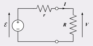
In electrical engineering, a practical electric power source which is a linear circuit may, according to Thévenin's theorem, be represented as an ideal voltage source in series with an impedance. This impedance is termed the internal resistance of the source. When the power source delivers current, the measured voltage output is lower than the no-load voltage; the difference is the voltage drop caused by the internal resistance. The concept of internal resistance applies to all kinds of electrical sources and is useful for analyzing many types of circuits.

Equivalent series inductance (ESL) is an effective inductance that is used to describe the inductive part of the impedance of certain electrical components.

<span class="mw-page-title-main">Capacitor types</span> Manufacturing styles of an electronic device

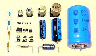
Capacitors are manufactured in many styles, forms, dimensions, and from a large variety of materials. They all contain at least two electrical conductors, called plates, separated by an insulating layer (dielectric). Capacitors are widely used as parts of electrical circuits in many common electrical devices.

<span class="mw-page-title-main">Q meter</span>

A Q meter is a piece of equipment used in the testing of radio frequency circuits. It has been largely replaced in professional laboratories by other types of impedance measuring devices, though it is still in use among radio amateurs. It was developed at Boonton Radio Corporation in Boonton, New Jersey in 1934 by William D. Loughlin.

Ripple in electronics is the residual periodic variation of the DC voltage within a power supply which has been derived from an alternating current (AC) source. This ripple is due to incomplete suppression of the alternating waveform after rectification. Ripple voltage originates as the output of a rectifier or from generation and commutation of DC power.

<span class="mw-page-title-main">Capacitor</span> Passive two-terminal electronic component that stores electrical energy in an electric field

A capacitor is an electronic device that stores electrical energy in an electric field by accumulating electric charges on two closely spaced surfaces that are insulated from each other. It is a passive electronic component with two terminals.

<span class="mw-page-title-main">Maxwell bridge</span>

A Maxwell bridge is a modification to a Wheatstone bridge used to measure an unknown inductance in terms of calibrated resistance and inductance or resistance and capacitance. When the calibrated components are a parallel resistor and capacitor, the bridge is known as a Maxwell bridge. It is named for James C. Maxwell, who first described it in 1873.

<span class="mw-page-title-main">Capacitance meter</span> Type of electronic test equipment

A capacitance meter is a piece of electronic test equipment used to measure capacitance, mainly of discrete capacitors. Depending on the sophistication of the meter, it may display the capacitance only, or it may also measure a number of other parameters such as leakage, equivalent series resistance (ESR), and inductance. For most purposes and in most cases the capacitor must be disconnected from circuit; ESR can usually be measured in circuit.

<span class="mw-page-title-main">Ceramic capacitor</span> Fixed-value capacitor using ceramic

A ceramic capacitor is a fixed-value capacitor where the ceramic material acts as the dielectric. It is constructed of two or more alternating layers of ceramic and a metal layer acting as the electrodes. The composition of the ceramic material defines the electrical behavior and therefore applications. Ceramic capacitors are divided into two application classes:

<span class="mw-page-title-main">LCR meter</span> Electronic test equipment that measures inductance, capacitance, and resistance

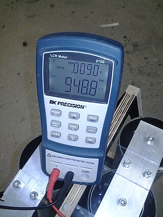
An LCR meter is a type of electronic test equipment used to measure the inductance (L), capacitance (C), and resistance (R) of an electronic component. In the simpler versions of this instrument the impedance was measured internally and converted for display to the corresponding capacitance or inductance value. Readings should be reasonably accurate if the capacitor or inductor device under test does not have a significant resistive component of impedance. More advanced designs measure true inductance or capacitance, as well as the equivalent series resistance of capacitors and the Q factor of inductive components.

<span class="mw-page-title-main">Applications of capacitors</span> Uses of capacitors in daily life

Capacitors have many uses in electronic and electrical systems. They are so ubiquitous that it is rare that an electrical product does not include at least one for some purpose. Capacitors allow only AC signals to pass when they are charged blocking DC signals. The main components of filters are capacitors. Capacitors have the ability to connect one circuit segment to another. Capacitors are used by Dynamic Random Access Memory (DRAM) devices to represent binary information as bits.

<span class="mw-page-title-main">Tantalum capacitor</span> Type of electrolytic capacitor

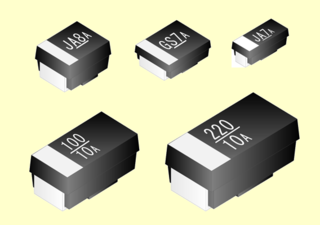
A tantalum electrolytic capacitor is an electrolytic capacitor, a passive component of electronic circuits. It consists of a pellet of porous tantalum metal as an anode, covered by an insulating oxide layer that forms the dielectric, surrounded by liquid or solid electrolyte as a cathode. Because of its very thin and relatively high permittivity dielectric layer, the tantalum capacitor distinguishes itself from other conventional and electrolytic capacitors in having high capacitance per volume and lower weight.

<span class="mw-page-title-main">ESR meter</span> Tool for measuring equivalent series resistance of capacitors

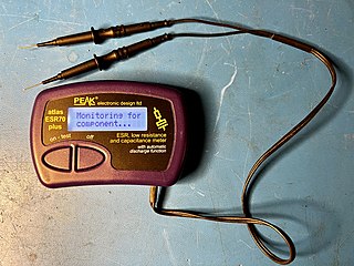
An ESR meter is a two-terminal electronic measuring instrument designed and used primarily to measure the equivalent series resistance (ESR) of real capacitors; usually without the need to disconnect the capacitor from the circuit it is connected to. Other types of meters used for routine servicing, including normal capacitance meters, cannot be used to measure a capacitor's ESR, although combined meters are available that measure both ESR and out-of-circuit capacitance. A standard (DC) milliohmmeter or multimeter cannot be used to measure ESR, because a steady direct current cannot be passed through the capacitor. Most ESR meters can also be used to measure non-inductive low-value resistances, whether or not associated with a capacitor; this leads to several additional applications described below.

<span class="mw-page-title-main">Polymer capacitor</span> Solid conductive electrolyte

A polymer capacitor, or more accurately a polymer electrolytic capacitor, is an electrolytic capacitor (e-cap) with a solid conductive polymer electrolyte. There are four different types:

<span class="mw-page-title-main">Film capacitor</span> Electrical capacitor with an insulating plastic film as the dielectric

Film capacitors, plastic film capacitors, film dielectric capacitors, or polymer film capacitors, generically called film caps as well as power film capacitors, are electrical capacitors with an insulating plastic film as the dielectric, sometimes combined with paper as carrier of the electrodes.

<span class="mw-page-title-main">SAL electrolytic capacitor</span> Capacitor with high capacitance in a small package

SAL electrolytic capacitors are a form of capacitor developed for high capacitance in a small package, with a long and robust service life. They are aluminum electrolytic capacitors with anodic oxidized aluminum oxide as dielectric and with the semiconducting solid manganese dioxide as electrolyte. They are made of etched and formed aluminum anodes, which are folded for the dipped pearl types or wound into a roll for the axial style. The solid manganese dioxide electrolyte is formed onto this roll in a pyrolytic process, similar to that for solid tantalum capacitors.
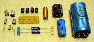
<span class="mw-page-title-main">Aluminum electrolytic capacitor</span> Type of capacitor

Aluminum electrolytic capacitors are polarized electrolytic capacitors whose anode electrode (+) is made of a pure aluminum foil with an etched surface. The aluminum forms a very thin insulating layer of aluminum oxide by anodization that acts as the dielectric of the capacitor. A non-solid electrolyte covers the rough surface of the oxide layer, serving in principle as the second electrode (cathode) (-) of the capacitor. A second aluminum foil called “cathode foil” contacts the electrolyte and serves as the electrical connection to the negative terminal of the capacitor.

<span class="mw-page-title-main">Niobium capacitor</span> Electrolytic capacitor

A niobium electrolytic capacitor is an electrolytic capacitor whose anode (+) is made of passivated niobium metal or niobium monoxide, on which an insulating niobium pentoxide layer acts as a dielectric. A solid electrolyte on the surface of the oxide layer serves as the capacitor's cathode (−).

References

  1. baldengineer (2019-06-19). "Measuring an aluminum electrolytic capacitor's ESR". Newark element14 . Archived from the original on 2023-02-01. Retrieved 2023-09-15.
  2. Capacitor Lab - Types of Capacitors - Polymer Capacitors.
  3. "Electronic Components distributor".
  4. "CapSite 2009 - ESR".