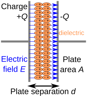
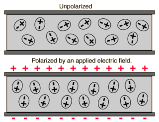
In electromagnetism, a dielectric is an electrical insulator that can be polarised by an applied electric field. When a dielectric material is placed in an electric field, electric charges do not flow through the material as they do in an electrical conductor, because they have no loosely bound, or free, electrons that may drift through the material, but instead they shift, only slightly, from their average equilibrium positions, causing dielectric polarisation. Because of dielectric polarisation, positive charges are displaced in the direction of the field and negative charges shift in the direction opposite to the field. This creates an internal electric field that reduces the overall field within the dielectric itself. If a dielectric is composed of weakly bonded molecules, those molecules not only become polarised, but also reorient so that their symmetry axes align to the field.
The propagation constant of a sinusoidal electromagnetic wave is a measure of the change undergone by the amplitude and phase of the wave as it propagates in a given direction. The quantity being measured can be the voltage, the current in a circuit, or a field vector such as electric field strength or flux density. The propagation constant itself measures the change per unit length, but it is otherwise dimensionless. In the context of two-port networks and their cascades, propagation constant measures the change undergone by the source quantity as it propagates from one port to the next.
The wave impedance of an electromagnetic wave is the ratio of the transverse components of the electric and magnetic fields. For a transverse-electric-magnetic (TEM) plane wave traveling through a homogeneous medium, the wave impedance is everywhere equal to the intrinsic impedance of the medium. In particular, for a plane wave travelling through empty space, the wave impedance is equal to the impedance of free space. The symbol Z is used to represent it and it is expressed in units of ohms. The symbol η (eta) may be used instead of Z for wave impedance to avoid confusion with electrical impedance.
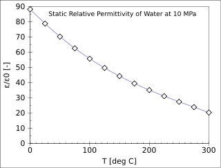
The relative permittivity is the permittivity of a material expressed as a ratio with the electric permittivity of a vacuum. A dielectric is an insulating material, and the dielectric constant of an insulator measures the ability of the insulator to store electric energy in an electrical field.
In electromagnetism, the absolute permittivity, often simply called permittivity and denoted by the Greek letter ε (epsilon), is a measure of the electric polarizability of a dielectric. A material with high permittivity polarizes more in response to an applied electric field than a material with low permittivity, thereby storing more energy in the material. In electrostatics, the permittivity plays an important role in determining the capacitance of a capacitor.

Capacitance is the ratio of the amount of electric charge stored on a conductor to a difference in electric potential. There are two closely related notions of capacitance: self capacitance and mutual capacitance. Any object that can be electrically charged exhibits self capacitance. In this case the electric potential difference is measured between the object and ground. A material with a large self capacitance holds more electric charge at a given potential difference than one with low capacitance. The notion of mutual capacitance is particularly important for understanding the operations of the capacitor, one of the three elementary linear electronic components. In a typical capacitor, two conductors are used to separate electric charge, with one conductor being positively charged and the other negatively charged, but the system having a total charge of zero. The ratio in this case is the magnitude of the electric charge on either conductor and the potential difference is that measured between the two conductors.
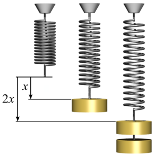
In physics, Hooke's law is an empirical law which states that the force needed to extend or compress a spring by some distance scales linearly with respect to that distance—that is, Fs = kx, where k is a constant factor characteristic of the spring, and x is small compared to the total possible deformation of the spring. The law is named after 17th-century British physicist Robert Hooke. He first stated the law in 1676 as a Latin anagram. He published the solution of his anagram in 1678 as: ut tensio, sic vis. Hooke states in the 1678 work that he was aware of the law since 1660.
Dynamic mechanical analysis is a technique used to study and characterize materials. It is most useful for studying the viscoelastic behavior of polymers. A sinusoidal stress is applied and the strain in the material is measured, allowing one to determine the complex modulus. The temperature of the sample or the frequency of the stress are often varied, leading to variations in the complex modulus; this approach can be used to locate the glass transition temperature of the material, as well as to identify transitions corresponding to other molecular motions.

The Drude model of electrical conduction was proposed in 1900 by Paul Drude to explain the transport properties of electrons in materials. Basically, Ohm's law was well established and stated that the current J and voltage V driving the current are related to the resistance R of the material. The inverse of the resistance is known as the conductance. When we consider a metal of unit length and unit cross sectional area, the conductance is known as the conductivity, which is the inverse of resistivity. The Drude model attempts to explain the resistivity of a conductor in terms of the scattering of electrons by the relatively immobile ions in the metal that act like obstructions to the flow of electrons.
In physics, the electric displacement field or electric induction is a vector field that appears in Maxwell's equations. It accounts for the effects of free and bound charge within materials. "D" stands for "displacement", as in the related concept of displacement current in dielectrics. In free space, the electric displacement field is equivalent to flux density, a concept that lends understanding of Gauss's law. In the International System of Units (SI), it is expressed in units of coulomb per meter square (C⋅m−2).

In quantum mechanics, a two-state system is a quantum system that can exist in any quantum superposition of two independent quantum states. The Hilbert space describing such a system is two-dimensional. Therefore, a complete basis spanning the space will consist of two independent states. Any two-state system can also be seen as a qubit.

Capacitors are manufactured in many forms, styles, lengths, girths, and from many materials. They all contain at least two electrical conductors separated by an insulating layer. Capacitors are widely used as parts of electrical circuits in many common electrical devices.
Dynamic modulus is the ratio of stress to strain under vibratory conditions. It is a property of viscoelastic materials.

A capacitor is a device that stores electrical energy in an electric field. It is a passive electronic component with two terminals.
Dielectric loss quantifies a dielectric material's inherent dissipation of electromagnetic energy. It can be parameterized in terms of either the loss angleδ or the corresponding loss tangent tan δ. Both refer to the phasor in the complex plane whose real and imaginary parts are the resistive (lossy) component of an electromagnetic field and its reactive (lossless) counterpart.
Defect types include atom vacancies, adatoms, steps, and kinks that occur most frequently at surfaces due to the finite material size causing crystal discontinuity. What all types of defects have in common, whether surface or bulk defects, is that they produce dangling bonds that have specific electron energy levels different from those of the bulk. This difference occurs because these states cannot be described with periodic Bloch waves due to the change in electron potential energy caused by the missing ion cores just outside the surface. Hence, these are localized states that require separate solutions to the Schrödinger equation so that electron energies can be properly described. The break in periodicity results in a decrease in conductivity due to defect scattering.

Surface plasmon polaritons (SPPs) are electromagnetic waves that travel along a metal–dielectric or metal–air interface, practically in the infrared or visible-frequency. The term "surface plasmon polariton" explains that the wave involves both charge motion in the metal and electromagnetic waves in the air or dielectric ("polariton").
Circuit quantum electrodynamics provides a means of studying the fundamental interaction between light and matter. As in the field of cavity quantum electrodynamics, a single photon within a single mode cavity coherently couples to a quantum object (atom). In contrast to cavity QED, the photon is stored in a one-dimensional on-chip resonator and the quantum object is no natural atom but an artificial one. These artificial atoms usually are mesoscopic devices which exhibit an atom-like energy spectrum. The field of circuit QED is a prominent example for quantum information processing and a promising candidate for future quantum computation.
Conductivity near the percolation threshold in physics, occurs in a mixture between a dielectric and a metallic component. The conductivity and the dielectric constant of this mixture show a critical behavior if the fraction of the metallic component reaches the percolation threshold.
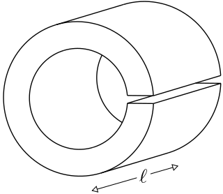
A loop-gap resonator (LGR) is an electromagnetic resonator that operates in the radio and microwave frequency ranges. The simplest LGRs are made from a conducting tube with a narrow slit cut along its length. The LGR dimensions are typically much smaller than the free-space wavelength of the electromagnetic fields at the resonant frequency. Therefore, relatively compact LGRs can be designed to operate at frequencies that are too low to be accessed using, for example, cavity resonators. These structures can have very sharp resonances making them useful for electron spin resonance (ESR) experiments, and precision measurements of electromagnetic material properties.


