This article needs additional citations for verification .(June 2021) |
Equivalent series inductance (ESL) is an effective inductance that is used to describe the inductive part of the impedance of certain electrical components. [1]
This article needs additional citations for verification .(June 2021) |
Equivalent series inductance (ESL) is an effective inductance that is used to describe the inductive part of the impedance of certain electrical components. [1]
The theoretical treatment of devices such as capacitors and resistors tends to assume they are ideal or "perfect" devices, contributing only capacitance or resistance to the circuit. However, all physical devices are connected to a circuit through conductive leads and paths, which contain inherent, usually unwanted, inductance. This means that physical components contain some inductance in addition to their other properties. [2]
An easy way to deal with these inherent inductances in circuit analysis is by using a lumped element model to express each physical component as a combination of an ideal component and a small inductor in series, the inductor having a value equal to the inductance present in the non-ideal, physical device.
Ideally, the impedance of a capacitor falls with increasing frequency at 20 dB/decade. However, due partly to the inductive properties of the connections, and partly to non-ideal characteristics of the capacitor material, real capacitors also have inductive properties whose impedance rises with frequency at 20 dB/decade. At the resonance frequency the sum of both is minimal, above it the parasitic series inductance of the capacitor dominates.

An electrical network is an interconnection of electrical components or a model of such an interconnection, consisting of electrical elements. An electrical circuit is a network consisting of a closed loop, giving a return path for the current. Thus all circuits are networks, but not all networks are circuits. Linear electrical networks, a special type consisting only of sources, linear lumped elements, and linear distributed elements, have the property that signals are linearly superimposable. They are thus more easily analyzed, using powerful frequency domain methods such as Laplace transforms, to determine DC response, AC response, and transient response.

An amplifier, electronic amplifier or (informally) amp is an electronic device that can increase the magnitude of a signal. It is a two-port electronic circuit that uses electric power from a power supply to increase the amplitude of a signal applied to its input terminals, producing a proportionally greater amplitude signal at its output. The amount of amplification provided by an amplifier is measured by its gain: the ratio of output voltage, current, or power to input. An amplifier is defined as a circuit that has a power gain greater than one.

In electrical engineering, impedance is the opposition to alternating current presented by the combined effect of resistance and reactance in a circuit.
In electrical circuits, reactance is the opposition presented to alternating current by inductance and capacitance. Along with resistance, it is one of two elements of impedance; however, while both elements involve transfer of electrical energy, no dissipation of electrical energy as heat occurs in reactance; instead, the reactance stores energy until a quarter-cycle later when the energy is returned to the circuit. Greater reactance gives smaller current for the same applied voltage.
In electrical engineering, electrical elements are conceptual abstractions representing idealized electrical components, such as resistors, capacitors, and inductors, used in the analysis of electrical networks. All electrical networks can be analyzed as multiple electrical elements interconnected by wires. Where the elements roughly correspond to real components, the representation can be in the form of a schematic diagram or circuit diagram. This is called a lumped-element circuit model. In other cases, infinitesimal elements are used to model the network in a distributed-element model.

A gyrator is a passive, linear, lossless, two-port electrical network element proposed in 1948 by Bernard D. H. Tellegen as a hypothetical fifth linear element after the resistor, capacitor, inductor and ideal transformer. Unlike the four conventional elements, the gyrator is non-reciprocal. Gyrators permit network realizations of two-(or-more)-port devices which cannot be realized with just the four conventional elements. In particular, gyrators make possible network realizations of isolators and circulators. Gyrators do not however change the range of one-port devices that can be realized. Although the gyrator was conceived as a fifth linear element, its adoption makes both the ideal transformer and either the capacitor or inductor redundant. Thus the number of necessary linear elements is in fact reduced to three. Circuits that function as gyrators can be built with transistors and op-amps using feedback.
Capacitors and inductors as used in electric circuits are not ideal components with only capacitance or inductance. However, they can be treated, to a very good degree of approximation, as being ideal capacitors and inductors in series with a resistance; this resistance is defined as the equivalent series resistance (ESR). If not otherwise specified, the ESR is always an AC resistance, which means it is measured at specified frequencies, 100 kHz for switched-mode power supply components, 120 Hz for linear power-supply components, and at its self-resonant frequency for general-application components. Additionally, audio components may report a "Q factor", incorporating ESR among other things, at 1000 Hz.

An LC circuit, also called a resonant circuit, tank circuit, or tuned circuit, is an electric circuit consisting of an inductor, represented by the letter L, and a capacitor, represented by the letter C, connected together. The circuit can act as an electrical resonator, an electrical analogue of a tuning fork, storing energy oscillating at the circuit's resonant frequency.
A Colpitts oscillator, invented in 1918 by Canadian-American engineer Edwin H. Colpitts using vacuum tubes, is one of a number of designs for LC oscillators, electronic oscillators that use a combination of inductors (L) and capacitors (C) to produce an oscillation at a certain frequency. The distinguishing feature of the Colpitts oscillator is that the feedback for the active device is taken from a voltage divider made of two capacitors in series across the inductor.

Capacitors are manufactured in many styles, forms, dimensions, and from a large variety of materials. They all contain at least two electrical conductors, called plates, separated by an insulating layer (dielectric). Capacitors are widely used as parts of electrical circuits in many common electrical devices.

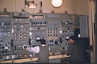
A Q meter is a piece of equipment used in the testing of radio frequency circuits. It has been largely replaced in professional laboratories by other types of impedance measuring devices, though it is still in use among radio amateurs. It was developed at Boonton Radio Corporation in Boonton, New Jersey in 1934 by William D. Loughlin.

In electronics, a decoupling capacitor is a capacitor used to decouple one part of a circuit from another. Noise caused by other circuit elements is shunted through the capacitor, reducing its effect on the rest of the circuit. For higher frequencies, an alternative name is bypass capacitor as it is used to bypass the power supply or other high-impedance component of a circuit.

In electrical engineering, a capacitor is a device that stores electrical energy by accumulating electric charges on two closely spaced surfaces that are insulated from each other. The capacitor was originally known as the condenser, a term still encountered in a few compound names, such as the condenser microphone. It is a passive electronic component with two terminals.
A bias tee is a three-port network used for setting the DC bias point of some electronic components without disturbing other components. The bias tee is a diplexer. The low-frequency port is used to set the bias; the high-frequency port passes the radio-frequency signals but blocks the biasing levels; the combined port connects to the device, which sees both the bias and RF. It is called a tee because the 3 ports are often arranged in the shape of a T.

A ceramic capacitor is a fixed-value capacitor where the ceramic material acts as the dielectric. It is constructed of two or more alternating layers of ceramic and a metal layer acting as the electrodes. The composition of the ceramic material defines the electrical behavior and therefore applications. Ceramic capacitors are divided into two application classes:
Zobel networks are a type of filter section based on the image-impedance design principle. They are named after Otto Zobel of Bell Labs, who published a much-referenced paper on image filters in 1923. The distinguishing feature of Zobel networks is that the input impedance is fixed in the design independently of the transfer function. This characteristic is achieved at the expense of a much higher component count compared to other types of filter sections. The impedance would normally be specified to be constant and purely resistive. For this reason, Zobel networks are also known as constant resistance networks. However, any impedance achievable with discrete components is possible.

A lattice phase equaliser or lattice filter is an example of an all-pass filter. That is, the attenuation of the filter is constant at all frequencies but the relative phase between input and output varies with frequency. The lattice filter topology has the particular property of being a constant-resistance network and for this reason is often used in combination with other constant-resistance filters such as bridge-T equalisers. The topology of a lattice filter, also called an X-section, is identical to bridge topology. The lattice phase equaliser was invented by Otto Zobel using a filter topology proposed by George Campbell.
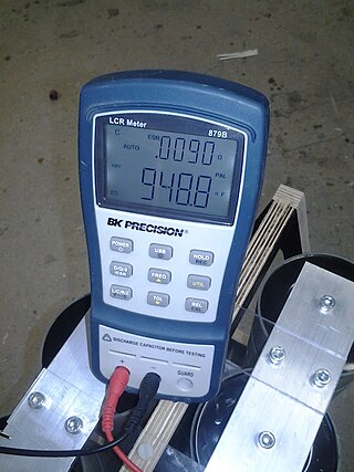
An LCR meter is a type of electronic test equipment used to measure the inductance (L), capacitance (C), and resistance (R) of an electronic component. In the simpler versions of this instrument the impedance was measured internally and converted for display to the corresponding capacitance or inductance value. Readings should be reasonably accurate if the capacitor or inductor device under test does not have a significant resistive component of impedance. More advanced designs measure true inductance or capacitance, as well as the equivalent series resistance of capacitors and the Q factor of inductive components.
Capacitors have many uses in electronic and electrical systems. They are so ubiquitous that it is rare that an electrical product does not include at least one for some purpose. Capacitors allow only AC signals to pass when they are charged blocking DC signals. The main components of filters are capacitors. Capacitors have the ability to connect one circuit segment to another. Capacitors are used by Dynamic Random Access Memory (DRAM) devices to represent binary information as bits.

The gyrator–capacitor model - sometimes also the capacitor-permeance model - is a lumped-element model for magnetic circuits, that can be used in place of the more common resistance–reluctance model. The model makes permeance elements analogous to electrical capacitance rather than electrical resistance. Windings are represented as gyrators, interfacing between the electrical circuit and the magnetic model.