ESR meter

Last updated
A typical ESR Meter. This one also measures capacitance. ESR Meter.jpg
A typical ESR Meter. This one also measures capacitance.

An ESR meter is a two-terminal electronic measuring instrument designed and used primarily to measure the equivalent series resistance (ESR) of real capacitors; usually without the need to disconnect the capacitor from the circuit it is connected to. Other types of meters used for routine servicing, including normal capacitance meters, cannot be used to measure a capacitor's ESR, although combined meters are available that measure both ESR and out-of-circuit capacitance. A standard (DC) milliohmmeter or multimeter cannot be used to measure ESR, because a steady direct current cannot be passed through the capacitor. Most ESR meters can also be used to measure non-inductive low-value resistances, whether or not associated with a capacitor; this leads to several additional applications described below.

Contents

Need for ESR measurement

Aluminium electrolytic capacitors have a relatively high ESR that increases with age, heat, and ripple current; this can cause the equipment using them to malfunction. In older equipment, this tended to cause hum and degraded operation; modern equipment, in particular switch-mode power supplies, is very sensitive to ESR, and a capacitor with high ESR can cause equipment to malfunction or cause permanent damage requiring repair, typically by causing power supply voltages to become excessively high. [1] Electrolytic capacitors are, nevertheless, very often used because they are inexpensive and have a very high capacitance per unit volume or weight; typically, these capacitors have capacitance from about one microfarad to tens of thousands of microfarads.

Capacitors with faults leading to high ESR often overheat and thereafter bulge and leak as the electrolyte chemicals decompose into gases, making them somewhat easy to identify visually; however, capacitors that appear visually perfect may still have high ESR, detectable only by measurement.

Precise measurement of ESR is rarely necessary, and any usable meter is adequate for troubleshooting. When precision is required, measurements must be taken under appropriately specified conditions, because ESR varies with frequency, applied voltage, and temperature. A general-purpose ESR meter operating with a fixed frequency and waveform will usually be unsuitable for precise laboratory measurements.

Methods of ESR measurement

Measuring ESR can be done by applying an alternating voltage at a frequency at which the capacitor's reactance is negligible, in a voltage divider configuration. It is easy to check ESR well enough for troubleshooting by using an improvised ESR meter comprising a simple square-wave generator and oscilloscope, or a sinewave generator of a few tens of kilohertz and an AC voltmeter, using a known good capacitor for comparison, or by using a little mathematics. [2]

A professional ESR meter is more convenient for checking multiple capacitors rapidly. A standard measurement bridge, and many LCR and Q meters, can also measure ESR accurately, in addition to many other circuit parameters. The dedicated ESR meter is a relatively inexpensive special-purpose instrument of modest accuracy, used mainly to identify capacitors with unacceptably large ESR and sometimes to measure other low resistances; measurements of other parameters cannot be made.

Principles of ESR meter operation

Most ESR meters work by discharging a real electrolytic capacitor (more or less equivalent to an ideal capacitor in series with an unwanted resistance, the ESR) and passing an electric current through it for a short time, too short for it to charge appreciably. This will produce a voltage across the device equal to the product of the current and the ESR plus a negligible contribution from a small charge in the capacitor; this voltage is measured and its value divided by the current (i.e., the ESR) shown in ohms or milliohms on a digital display or by the position of a pointer on a scale. The process is repeated tens or hundreds of thousands of times a second.

Alternatively, an alternating current at a frequency high enough that the capacitor's reactance is much less than the ESR can be used. Circuit parameters are usually chosen to give meaningful results for capacitance from about one microfarad up, a range that covers typical aluminium capacitors whose ESR tends to become unacceptably high.

Interpretation of readings

An acceptable ESR value depends upon capacitance (larger capacitors usually have lower ESR) and may be read from a table of "typical" values, or compared with a new component. In principle, the capacitor manufacturer's upper limit specification for ESR can be looked up in a datasheet, but this is usually unnecessary. When a capacitor whose ESR is critical degrades, power dissipation as the ESR increases usually causes a rapid and large runaway increase, so go/no-go measurement is usually good enough as the ESR often rapidly moves from a clearly acceptable to a clearly unacceptable level; an ESR of over a few ohms (less for a large capacitor) is unacceptable.

In a practical circuit, the ESR will be much lower than any other resistance in parallel with the capacitor, so it is not necessary to disconnect the component, and an in-circuit measurement can be made. Practical ESR meters use a voltage too low to switch on any semiconductor junctions that may be present in the circuit; this might present a low "on" impedance that would interfere with measurements.

Limitations

Other uses of ESR meters

An ESR meter is more accurately described as a pulsed or high-frequency AC milliohmmeter (depending upon type), and it can be used to measure any low resistance. An ESR meter with no back-to-back protective diodes across its input can measure the internal resistance of batteries (many batteries end their useful life largely due to increased internal resistance, rather than low EMF). Depending upon the exact circuit used, an ESR meter may also be used to measure the contact resistance of switches, the resistance of sections of printed circuit (PCB) track, etc.

While there are specialised instruments to detect short circuits between adjacent PCB tracks, an ESR meter is useful because it can measure low resistances while injecting a voltage too low to confuse readings by switching on semiconductor junctions in the circuit. An ESR meter can be used to find short circuits, even finding which of a group of capacitors or transistors connected in parallel by printed circuit tracks or wires is short-circuited. Many conventional ohmmeters and multimeters are not usable for very low resistances, and those capable of measuring low resistance typically use a voltage high enough to switch on semiconductor junctions, [3] falsifying resistance readings.

Tweezer probes are useful when test points are closely spaced, such as in equipment made with surface mount technology. The tweezer probes can be held in one hand, leaving the other hand free to steady or manipulate the equipment being tested.

History

The first major device to measure in-circuit ESR was based on Carl W. Vette's 1978 "US Patent #4216424: Method and apparatus for testing electrolytic capacitors". [4] under the Creative Electronics brand. The Creative Electronics ESR meter was the primary device many used for the duration of the patent. The patent expired in 1998 when many other companies entered the market.

Additional patents extended the original work, including John G. Bachman's 2001 "US Patent #6677764: System for protecting electronic test equipment from charged capacitors". [5]

See also

Related Research Articles

<span class="mw-page-title-main">Ammeter</span> Device that measures electric current

An ammeter is an instrument used to measure the current in a circuit. Electric currents are measured in amperes (A), hence the name. For direct measurement, the ammeter is connected in series with the circuit in which the current is to be measured. An ammeter usually has low resistance so that it does not cause a significant voltage drop in the circuit being measured.

<span class="mw-page-title-main">Voltmeter</span> Instrument used for measuring voltage

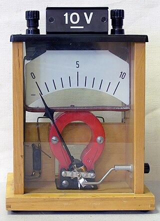
A voltmeter is an instrument used for measuring electric potential difference between two points in an electric circuit. It is connected in parallel. It usually has a high resistance so that it takes negligible current from the circuit.

<span class="mw-page-title-main">Ohmmeter</span> Tool for measuring electrical resistance

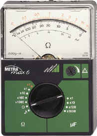
An ohmmeter is an electrical instrument that measures electrical resistance. Multimeters also function as ohmmeters when in resistance-measuring mode. An ohmmeter applies current to the circuit or component whose resistance is to be measured. It then measures the resulting voltage and calculates the resistance using Ohm’s law .

<span class="mw-page-title-main">Multimeter</span> Electronic measuring instrument that combines several measurement functions in one unit

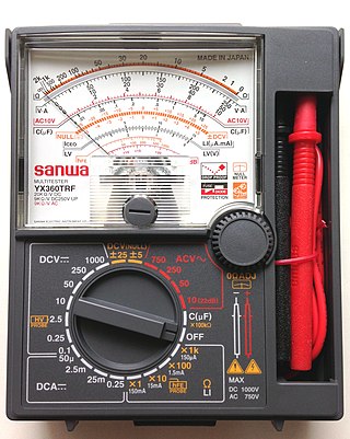
A multimeter is a measuring instrument that can measure multiple electrical properties. A typical multimeter can measure voltage, resistance, and current, in which case can be used as a voltmeter, ohmmeter, and ammeter. Some feature the measurement of additional properties such as temperature and capacitance.

<span class="mw-page-title-main">Electronic test equipment</span> Testing appliance for electronics systems

Electronic test equipment is used to create signals and capture responses from electronic devices under test (DUTs). In this way, the proper operation of the DUT can be proven or faults in the device can be traced. Use of electronic test equipment is essential to any serious work on electronics systems.

A photoflash capacitor is a high-voltage electrolytic capacitor used in camera flashes and in solid-state laser power supplies. Their usual purpose is to briefly power a flash lamp, used to illuminate a photographic subject or optically pump a laser rod. As flash tubes require very high current for a very short time to operate, photoflash capacitors are designed to supply high discharge current pulses without excessive internal heating.

<span class="mw-page-title-main">Electrolytic capacitor</span> Type of capacitor

An electrolytic capacitor is a polarized capacitor whose anode or positive plate is made of a metal that forms an insulating oxide layer through anodization. This oxide layer acts as the dielectric of the capacitor. A solid, liquid, or gel electrolyte covers the surface of this oxide layer, serving as the cathode or negative plate of the capacitor. Because of their very thin dielectric oxide layer and enlarged anode surface, electrolytic capacitors have a much higher capacitance-voltage (CV) product per unit volume than ceramic capacitors or film capacitors, and so can have large capacitance values. There are three families of electrolytic capacitor: aluminium electrolytic capacitors, tantalum electrolytic capacitors, and niobium electrolytic capacitors.

<span class="mw-page-title-main">Internal resistance</span> Impedance of a linear circuits Thévenin representation

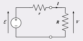
In electrical engineering, a practical electric power source which is a linear circuit may, according to Thévenin's theorem, be represented as an ideal voltage source in series with an impedance. This impedance is termed the internal resistance of the source. When the power source delivers current, the measured voltage output is lower than the no-load voltage; the difference is the voltage drop caused by the internal resistance. The concept of internal resistance applies to all kinds of electrical sources and is useful for analyzing many types of circuits.

<span class="mw-page-title-main">Capacitor types</span> Manufacturing styles of an electronic device

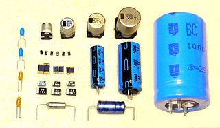
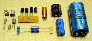
Capacitors are manufactured in many styles, forms, dimensions, and from a large variety of materials. They all contain at least two electrical conductors, called plates, separated by an insulating layer (dielectric). Capacitors are widely used as parts of electrical circuits in many common electrical devices.

<span class="mw-page-title-main">Q meter</span>

A Q meter is a piece of equipment used in the testing of radio frequency circuits. It has been largely replaced in professional laboratories by other types of impedance measuring devices, though it is still in use among radio amateurs. It was developed at Boonton Radio Corporation in Boonton, New Jersey in 1934 by William D. Loughlin.

<span class="mw-page-title-main">Capacitor</span> Passive two-terminal electronic component that stores electrical energy in an electric field

In electrical engineering, a capacitor is a device that stores electrical energy by accumulating electric charges on two closely spaced surfaces that are insulated from each other. The capacitor was originally known as the condenser, a term still encountered in a few compound names, such as the condenser microphone. It is a passive electronic component with two terminals.

<span class="mw-page-title-main">Capacitance meter</span> Type of electronic test equipment

A capacitance meter is a piece of electronic test equipment used to measure capacitance, mainly of discrete capacitors. Depending on the sophistication of the meter, it may display the capacitance only, or it may also measure a number of other parameters such as leakage, equivalent series resistance (ESR), and inductance. For most purposes and in most cases the capacitor must be disconnected from circuit; ESR can usually be measured in circuit.

<span class="mw-page-title-main">Test probe</span>

A test probe is a physical device used to connect electronic test equipment to a device under test (DUT). Test probes range from very simple, robust devices to complex probes that are sophisticated, expensive, and fragile. Specific types include test prods, oscilloscope probes and current probes. A test probe is often supplied as a test lead, which includes the probe, cable and terminating connector.

<span class="mw-page-title-main">Ceramic capacitor</span> Fixed-value capacitor using ceramic

A ceramic capacitor is a fixed-value capacitor where the ceramic material acts as the dielectric. It is constructed of two or more alternating layers of ceramic and a metal layer acting as the electrodes. The composition of the ceramic material defines the electrical behavior and therefore applications. Ceramic capacitors are divided into two application classes:

<span class="mw-page-title-main">LCR meter</span> Electronic test equipment that measures inductance, capacitance, and resistance

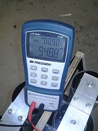
An LCR meter is a type of electronic test equipment used to measure the inductance (L), capacitance (C), and resistance (R) of an electronic component. In the simpler versions of this instrument the impedance was measured internally and converted for display to the corresponding capacitance or inductance value. Readings should be reasonably accurate if the capacitor or inductor device under test does not have a significant resistive component of impedance. More advanced designs measure true inductance or capacitance, as well as the equivalent series resistance of capacitors and the Q factor of inductive components.

<span class="mw-page-title-main">Applications of capacitors</span> Uses of capacitors in daily life

Capacitors have many uses in electronic and electrical systems. They are so ubiquitous that it is rare that an electrical product does not include at least one for some purpose. Capacitors allow only AC signals to pass when they are charged blocking DC signals. The main components of filters are capacitors. Capacitors have the ability to connect one circuit segment to another. Capacitors are used by Dynamic Random Access Memory (DRAM) devices to represent binary information as bits.

<span class="mw-page-title-main">Tantalum capacitor</span> Type of electrolytic capacitor

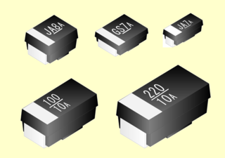
A tantalum electrolytic capacitor is an electrolytic capacitor, a passive component of electronic circuits. It consists of a pellet of porous tantalum metal as an anode, covered by an insulating oxide layer that forms the dielectric, surrounded by liquid or solid electrolyte as a cathode. Because of its very thin and relatively high permittivity dielectric layer, the tantalum capacitor distinguishes itself from other conventional and electrolytic capacitors in having high capacitance per volume and lower weight.

<span class="mw-page-title-main">Film capacitor</span> Electrical capacitor with an insulating plastic film as the dielectric

Film capacitors, plastic film capacitors, film dielectric capacitors, or polymer film capacitors, generically called film caps as well as power film capacitors, are electrical capacitors with an insulating plastic film as the dielectric, sometimes combined with paper as carrier of the electrodes.

<span class="mw-page-title-main">Aluminum electrolytic capacitor</span> Type of capacitor

Aluminum electrolytic capacitors are (usually) polarized electrolytic capacitors whose anode electrode (+) is made of a pure aluminum foil with an etched surface. The aluminum forms a very thin insulating layer of aluminum oxide by anodization that acts as the dielectric of the capacitor. A non-solid electrolyte covers the rough surface of the oxide layer, serving in principle as the second electrode (cathode) (-) of the capacitor. A second aluminum foil called "cathode foil" contacts the electrolyte and serves as the electrical connection to the negative terminal of the capacitor.

<span class="mw-page-title-main">Niobium capacitor</span> Electrolytic capacitor

A niobium electrolytic capacitor is an electrolytic capacitor whose anode (+) is made of passivated niobium metal or niobium monoxide, on which an insulating niobium pentoxide layer acts as a dielectric. A solid electrolyte on the surface of the oxide layer serves as the capacitor's cathode (−).

References

  1. Example of high-ESR capacitors causing voltages to rise in a circuit and destroy components. Archived 2013-10-29 at the Wayback Machine High ESR capacitors cause "5V dropping quite low and causing every other voltage to go sky high (and doing things like frying the HDD with upwards of 15V rather than 12V, and frying the tuning agc transistor with upwards of 36V instead of 30V)."
  2. Stephen M. Powell (2000). "99 cent ESR test adapter". Archived from the original on 2010-01-28. Retrieved 2019-05-28.
  3. Kuphaldt, Tony R. (12 February 2015). "Meter Check of a Transistor (BJT) - Bipolar Junction Transistors". Electronics Textbook.
  4. Carl W. Vette (1978). "US Patent #4216424: Method and apparatus for testing electrolytic capacitors "
  5. John G. Bachman (2001). "US Patent #6677764: System for protecting electronic test equipment from charged capacitors"