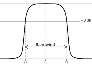
In physics and electrical engineering, a cutoff frequency, corner frequency, or break frequency is a boundary in a system's frequency response at which energy flowing through the system begins to be reduced rather than passing through.
A low-pass filter is a filter that passes signals with a frequency lower than a selected cutoff frequency and attenuates signals with frequencies higher than the cutoff frequency. The exact frequency response of the filter depends on the filter design. The filter is sometimes called a high-cut filter, or treble-cut filter in audio applications. A low-pass filter is the complement of a high-pass filter.

In electrical engineering and control theory, a Bode plot is a graph of the frequency response of a system. It is usually a combination of a Bode magnitude plot, expressing the magnitude of the frequency response, and a Bode phase plot, expressing the phase shift.
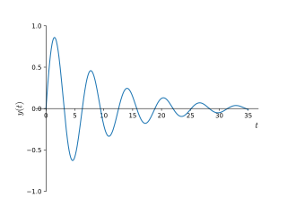
In physics and engineering, the quality factor or Q factor is a dimensionless parameter that describes how underdamped an oscillator or resonator is. It is defined as the ratio of the initial energy stored in the resonator to the energy lost in one radian of the cycle of oscillation. Q factor is alternatively defined as the ratio of a resonator's centre frequency to its bandwidth when subject to an oscillating driving force. These two definitions give numerically similar, but not identical, results. Higher Q indicates a lower rate of energy loss and the oscillations die out more slowly. A pendulum suspended from a high-quality bearing, oscillating in air, has a high Q, while a pendulum immersed in oil has a low one. Resonators with high quality factors have low damping, so that they ring or vibrate longer.
A resistor–capacitor circuit, or RC filter or RC network, is an electric circuit composed of resistors and capacitors. It may be driven by a voltage or current source and these will produce different responses. A first order RC circuit is composed of one resistor and one capacitor and is the simplest type of RC circuit.
Chebyshev filters are analog or digital filters that have a steeper roll-off than Butterworth filters, and have either passband ripple or stopband ripple. Chebyshev filters have the property that they minimize the error between the idealized and the actual filter characteristic over the operating frequency range of the filter, but they achieve this with ripples in the passband. This type of filter is named after Pafnuty Chebyshev because its mathematical characteristics are derived from Chebyshev polynomials. Type I Chebyshev filters are usually referred to as "Chebyshev filters", while type II filters are usually called "inverse Chebyshev filters". Because of the passband ripple inherent in Chebyshev filters, filters with a smoother response in the passband but a more irregular response in the stopband are preferred for certain applications.

The short-time Fourier transform (STFT) is a Fourier-related transform used to determine the sinusoidal frequency and phase content of local sections of a signal as it changes over time. In practice, the procedure for computing STFTs is to divide a longer time signal into shorter segments of equal length and then compute the Fourier transform separately on each shorter segment. This reveals the Fourier spectrum on each shorter segment. One then usually plots the changing spectra as a function of time, known as a spectrogram or waterfall plot, such as commonly used in software defined radio (SDR) based spectrum displays. Full bandwidth displays covering the whole range of an SDR commonly use fast Fourier transforms (FFTs) with 2^24 points on desktop computers.
Sound pressure or acoustic pressure is the local pressure deviation from the ambient atmospheric pressure, caused by a sound wave. In air, sound pressure can be measured using a microphone, and in water with a hydrophone. The SI unit of sound pressure is the pascal (Pa).
Particle velocity is the velocity of a particle in a medium as it transmits a wave. The SI unit of particle velocity is the metre per second (m/s). In many cases this is a longitudinal wave of pressure as with sound, but it can also be a transverse wave as with the vibration of a taut string.

The Butterworth filter is a type of signal processing filter designed to have a frequency response that is as flat as possible in the passband. It is also referred to as a maximally flat magnitude filter. It was first described in 1930 by the British engineer and physicist Stephen Butterworth in his paper entitled "On the Theory of Filter Amplifiers".
A resistor–inductor circuit, or RL filter or RL network, is an electric circuit composed of resistors and inductors driven by a voltage or current source. A first-order RL circuit is composed of one resistor and one inductor, either in series driven by a voltage source or in parallel driven by a current source. It is one of the simplest analogue infinite impulse response electronic filters.
An isotropic radiator is a theoretical point source of waves which radiates the same intensity of radiation in all directions. It may be based on sound waves or electromagnetic waves, in which case it is also known as an isotropic antenna. It has no preferred direction of radiation, i.e., it radiates uniformly in all directions over a sphere centred on the source.

The Optimum "L" filter was proposed by Athanasios Papoulis in 1958. It has the maximum roll off rate for a given filter order while maintaining a monotonic frequency response. It provides a compromise between the Butterworth filter which is monotonic but has a slower roll off and the Chebyshev filter which has a faster roll off but has ripple in either the passband or stopband. The filter design is based on Legendre polynomials which is the reason for its alternate name and the "L" in Optimum "L".
Ripple in electronics is the residual periodic variation of the DC voltage within a power supply which has been derived from an alternating current (AC) source. This ripple is due to incomplete suppression of the alternating waveform after rectification. Ripple voltage originates as the output of a rectifier or from generation and commutation of DC power.

In thermodynamics, the fundamental thermodynamic relation are four fundamental equations which demonstrate how four important thermodynamic quantities depend on variables that can be controlled and measured experimentally. Thus, they are essentially equations of state, and using the fundamental equations, experimental data can be used to determine sought-after quantities like G or H (enthalpy). The relation is generally expressed as a microscopic change in internal energy in terms of microscopic changes in entropy, and volume for a closed system in thermal equilibrium in the following way.
Zobel networks are a type of filter section based on the image-impedance design principle. They are named after Otto Zobel of Bell Labs, who published a much-referenced paper on image filters in 1923. The distinguishing feature of Zobel networks is that the input impedance is fixed in the design independently of the transfer function. This characteristic is achieved at the expense of a much higher component count compared to other types of filter sections. The impedance would normally be specified to be constant and purely resistive. For this reason, Zobel networks are also known as constant resistance networks. However, any impedance achievable with discrete components is possible.

Prototype filters are electronic filter designs that are used as a template to produce a modified filter design for a particular application. They are an example of a nondimensionalised design from which the desired filter can be scaled or transformed. They are most often seen in regard to electronic filters and especially linear analogue passive filters. However, in principle, the method can be applied to any kind of linear filter or signal processing, including mechanical, acoustic and optical filters.
The primary line constants are parameters that describe the characteristics of conductive transmission lines, such as pairs of copper wires, in terms of the physical electrical properties of the line. The primary line constants are only relevant to transmission lines and are to be contrasted with the secondary line constants, which can be derived from them, and are more generally applicable. The secondary line constants can be used, for instance, to compare the characteristics of a waveguide to a copper line, whereas the primary constants have no meaning for a waveguide.
An RLC circuit is an electrical circuit consisting of a resistor (R), an inductor (L), and a capacitor (C), connected in series or in parallel. The name of the circuit is derived from the letters that are used to denote the constituent components of this circuit, where the sequence of the components may vary from RLC.
Staggered tuning is a technique used in the design of multi-stage tuned amplifiers whereby each stage is tuned to a slightly different frequency. In comparison to synchronous tuning it produces a wider bandwidth at the expense of reduced gain. It also produces a sharper transition from the passband to the stopband. Both staggered tuning and synchronous tuning circuits are easier to tune and manufacture than many other filter types.

![Roll-off of a first-order low-pass filter is 20 dB/decade ([?]6 dB/octave) Roll-off graph 6dB.svg](http://upload.wikimedia.org/wikipedia/commons/thumb/8/88/Roll-off_graph_6dB.svg/250px-Roll-off_graph_6dB.svg.png)


