An electronic symbol is a pictogram used to represent various electrical and electronic devices or functions, such as wires, batteries, resistors, and transistors, in a schematic diagram of an electrical or electronic circuit. These symbols are largely standardized internationally today, but may vary from country to country, or engineering discipline, based on traditional conventions.
Contents
- Standards for symbols
- Common electronic symbols
- Traces
- Grounds
- Sources
- Resistors
- Capacitors
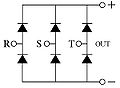
- Diodes
- Inductors
- Transformers
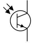
- Transistors
- Vacuum tubes
- Switches
- Relays
- Lamps
- Current limiters
- Voltage limiters
- Electro-acoustic devices
- Antennas
- Cables
- Connectors
- ICs
- Oscillators
- Miscellaneous devices
- Historical electronic symbols
- Capacitors (historical)
- See also
- References
- Further reading
- External links