UEXT

Last updated
UEXT
Type Digital electronics
Production history
Designer Olimex
Produced 2004
Audio signal None
Video signal None
Electrical
Signal 3.3 volt
Data
Protocol Serial: UART / I2C / SPI

Universal EXTension (UEXT) is a connector layout which includes power and three serial buses: Asynchronous, I2C, and SPI separately over 10 pins in a 2x5 layout. The connector layout was specified by Olimex Ltd and declared an open-project that is royalty-free in 2011, and was used in all their boards after 2004. [1]

Contents

Physical characteristics

The UEXT connector consists of 10 pins, in a two row by five male pin configuration, with a plastic keyed-shrouded or box header (specifically BH10S). All pins have a spacing of 0.1 inch (2.54 mm). [1] [2] The socket is mated with a 2x5 (10-pin) IDC female connector, and typically connected to a Ribbon cable. The UEXT cable assembly is referred to as a 10-pin IDC Connector Ribbon Cable. These cables are readily available and cheap. [3]

Electrical characteristics

UEXT pinout for IDC connector
(looking into connector on host board) UEXTPINS.jpg
UEXT pinout for IDC connector
(looking into connector on host board)

The UEXT connector presents power and three serial buses: Asynchronous, I2C, SPI. [1] All pins conform to 3.3 volt digital logic. The asynchronous serial bus requires additional level-shifting circuits and connectors to support RS-232, RS-422, RS-485, DMX512, or MIDI.

UEXT Connector
PinNameI/OLogicPrimary Use
13.3VSS+3.3 volt
2GNDSSGround
3TXDOPPTransmit Data for Async Serial bus
4RXDIPPReceive Data for Async Serial bus
5SCLOODClock for I2C bus
6SDAI/OODBidirectional Serial Data for I2C bus
7MISOIPPSerial Data In for SPI bus
8MOSIOPPSerial Data Out for SPI bus
9SCKOPP Clock for SPI bus
10/SSELOPP Chip Select for SPI bus

Notes:

  1. Direction is relative to host board. [1] I = Input, O = Output.
  2. S = Power Supply, PP = Push-Pull logic, OD = Open-Drain logic, all pins conform to 3.3 volt digital logic

Alternate pin uses

The functionality of most microcontroller pins are multipurpose, thus allowing the engineer to redefine the purpose of the pin. It is fairly common that a pin will have a choice to be either a general purpose I/O or a peripheral.

If a microcontroller pin is connected to the UEXT connector and redefined to be something other than Asynchronous Serial Bus / I2C Bus / SPI Bus, then some thought should be given to the design before making the changes. To minimize the chance of damaging various UEXT boards or the microcontroller, redefined pins should continue to adhere to the direction of the data in this table or alternately redefined as an input. For a safe design, it is recommended that you don't redefine pins 4 or 7 to be outputs, and use pin 6 as an output with caution.

User concerns

Olimex LPC-E2468, showing UEXT connector Uext.jpg
Olimex LPC-E2468, showing UEXT connector

If a person is concerned about damaging the data lines of the microcontroller, additional over-voltage protection diodes and/or separate drivers should be added between the microcontroller and UEXT connector. Additionally, a resettable fuse might be added between the host power and pin 1 to protect against over-current conditions. Open source UART dongles are available that are explicitly designed to be pin compatible with UEXT, [4] and may be used to interface a UEXT device directly with a computer over USB.

5V warning

Some boards might provide 5V output on UEXT pins if they are configured for operation at 5V. For example, OLIMEXINO-328 and OLIMEXINO-32U4 have a 3.3V/5V PTH jumper that changes the power mode of the board. If the 3.3V/5V jumper is set to 5V, this jumper also changes the voltage available at pin #1 of UEXT as well as the voltage levels of all data signals available there (UART, SPI, I2C). As the UEXT standard only defines 3.3V, many UEXT modules may not be 5V tolerant, and thus get damaged if the board has such jumper set to 5V. Users are advised to verify their boards are configured for 3.3V before connecting UEXT hardware to prevent damaging said hardware.

Parallel cables

It is possible to connect multiple UEXT devices in parallel by clamping additional IDC connectors onto the same ribbon cable. This will result in a correct distribution of power (3.3V and ground) and allow data communication over I²C.

However, a multidrop SPI bus will fail since all the chip selects are tied together, thus all peripherals will be addressed simultaneously resulting in their simultaneous response data on the MISO line being scrambled. UART will also fail due to multiple devices transmitting and receiving on the same lines. Series resistors are necessary on conflicting SPI and UART pins to limit short circuit currents due to conflicts, if compatibility with other UEXT devices is desired.

Similar connectors

Some devices use a layout based on the UEXT connector but have chosen not to implement all of the functionality. In particular the asynchronous serial connection may have been omitted. In these cases the spare pins are usually assigned other purposes, such as connecting to a device reset line, so care should be taken to check the exact connector layout on the schematic of a particular device.

Implementations

UEXT I/O Boards
Host Boards
3rd-party

See also

Related Research Articles

<span class="mw-page-title-main">Universal asynchronous receiver-transmitter</span> Computer hardware device

A universal asynchronous receiver-transmitter is a computer hardware device for asynchronous serial communication in which the data format and transmission speeds are configurable. It sends data bits one by one, from the least significant to the most significant, framed by start and stop bits so that precise timing is handled by the communication channel. The electric signaling levels are handled by a driver circuit external to the UART. Common signal levels are RS-232, RS-485, and raw TTL for short debugging links. Early teletypewriters used current loops.

<span class="mw-page-title-main">Serial port</span> Communication interface transmitting information sequentially

On computers, a serial port is a serial communication interface through which information transfers in or out sequentially one bit at a time. This is in contrast to a parallel port, which communicates multiple bits simultaneously in parallel. Throughout most of the history of personal computers, data has been transferred through serial ports to devices such as modems, terminals, various peripherals, and directly between computers.

<span class="mw-page-title-main">AVR microcontrollers</span> Family of microcontrollers

AVR is a family of microcontrollers developed since 1996 by Atmel, acquired by Microchip Technology in 2016. These are modified Harvard architecture 8-bit RISC single-chip microcontrollers. AVR was one of the first microcontroller families to use on-chip flash memory for program storage, as opposed to one-time programmable ROM, EPROM, or EEPROM used by other microcontrollers at the time.

<span class="mw-page-title-main">Serial communication</span> Type of data transfer

In telecommunication and data transmission, serial communication is the process of sending data one bit at a time, sequentially, over a communication channel or computer bus. This is in contrast to parallel communication, where several bits are sent as a whole, on a link with several parallel channels.

Serial Peripheral Interface (SPI) is a de facto standard for synchronous serial communication, used primarily in embedded systems for short-distance wired communication between integrated circuits.

<span class="mw-page-title-main">1-Wire</span> Device communications bus system

1-Wire is a wired half duplex serial bus designed by Dallas Semiconductor that provides low-speed (16.3 kbit/s) data communication and supply voltage over a single conductor.

JTAG is an industry standard for verifying designs and testing printed circuit boards after manufacture.

<span class="mw-page-title-main">PICAXE</span>

PICAXE is a microcontroller system based on a range of Microchip PIC microcontrollers. PICAXE devices are Microchip PIC devices with pre-programmed firmware that enables bootloading of code directly from a PC, simplifying hobbyist embedded development. PICAXE devices have been produced by Revolution Education (Rev-Ed) since 1999.

In computer engineering and electrical engineering, bit banging is a "term of art" for any method of data transmission that employs software as a substitute for dedicated hardware to generate transmitted signals or process received signals. Software directly sets and samples the states of GPIOs, and is responsible for meeting all timing requirements and protocol sequencing of the signals. In contrast to bit banging, dedicated hardware satisfies these requirements and, if necessary, provides a data buffer to relax software timing requirements. Bit banging can be implemented at very low cost, and is commonly used in some embedded systems.

<span class="mw-page-title-main">Parallel SCSI</span> Original SCSI storage interface

Parallel SCSI is the earliest of the interface implementations in the SCSI family. SPI is a parallel bus; there is one set of electrical connections stretching from one end of the SCSI bus to the other. A SCSI device attaches to the bus but does not interrupt it. Both ends of the bus must be terminated.

Tolapai is the code name of Intel's embedded system on a chip (SoC) which combines a Pentium M (Dothan) processor core, DDR2 memory controllers and input/output (I/O) controllers, and a QuickAssist integrated accelerator unit for security functions.

<span class="mw-page-title-main">ChibiOS/RT</span> Real-time operating system

ChibiOS/RT is a compact and fast real-time operating system supporting multiple architectures and released under a mix of the GNU General Public License version 3 (GPL3) and the Apache License 2.0. It is developed by Giovanni Di Sirio.

<span class="mw-page-title-main">Bus Pirate</span> Microcontroller programmer and debugger

The Bus Pirate is a universal bus interface device designed for programming, debugging, and analyzing microcontrollers and other ICs. It was developed as an open-source hardware and software project.

<span class="mw-page-title-main">STM32</span> ARM Cortex-M based Microcontrollers by STMicroelectronics

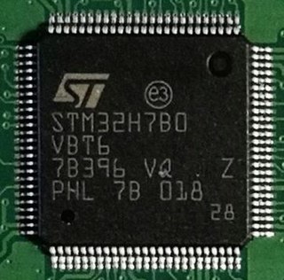
STM32 is a family of 32-bit microcontroller integrated circuits by STMicroelectronics. The STM32 chips are grouped into related series that are based around the same 32-bit ARM processor core: Cortex-M0, Cortex-M0+, Cortex-M3, Cortex-M4, Cortex-M7, Cortex-M33. Internally, each microcontroller consists of ARM processor core(s), flash memory, static RAM, debugging interface, and various peripherals.

<span class="mw-page-title-main">NXP LPC</span> Family of 32-bit microcontroller integrated circuits

LPC is a family of 32-bit microcontroller integrated circuits by NXP Semiconductors. The LPC chips are grouped into related series that are based around the same 32-bit ARM processor core, such as the Cortex-M4F, Cortex-M3, Cortex-M0+, or Cortex-M0. Internally, each microcontroller consists of the processor core, static RAM memory, flash memory, debugging interface, and various peripherals. The earliest LPC series were based on the Intel 8-bit 80C51 core. As of February 2011, NXP had shipped over one billion ARM processor-based chips.

Pmod interface is an open standard defined by Digilent in the Pmod Interface Specification for connecting peripheral modules to FPGA and microcontroller development boards using 6 pins. Pmod or Pmods may also refer to modules compatible with the Pmod interface.

<span class="mw-page-title-main">Arduino Uno</span> Microcontroller board

The Arduino Uno is an open-source microcontroller board based on the Microchip ATmega328P microcontroller (MCU) and developed by Arduino.cc and initially released in 2010. The microcontroller board is equipped with sets of digital and analog input/output (I/O) pins that may be interfaced to various expansion boards (shields) and other circuits. The board has 14 digital I/O pins, 6 analog I/O pins, and is programmable with the Arduino IDE, via a type B USB cable. It can be powered by a USB cable or a barrel connector that accepts voltages between 7 and 20 volts, such as a rectangular 9-volt battery. It has the same microcontroller as the Arduino Nano board, and the same headers as the Leonardo board. The hardware reference design is distributed under a Creative Commons Attribution Share-Alike 2.5 license and is available on the Arduino website. Layout and production files for some versions of the hardware are also available.

<span class="mw-page-title-main">ESP8266</span> System-on-a-chip microcontroller model with Wi-Fi

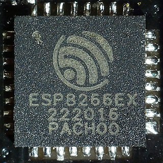
The ESP8266 is a low-cost Wi-Fi microchip, with built-in TCP/IP networking software, and microcontroller capability, produced by Espressif Systems in Shanghai, China.

<span class="mw-page-title-main">Arduino Nano</span> Single-board microcontroller

The Arduino Nano is an open-source breadboard-friendly microcontroller board based on the Microchip ATmega328P microcontroller (MCU) and developed by Arduino.cc and initially released in 2008. It offers the same connectivity and specs of the Arduino Uno board in a smaller form factor.

References

  1. 1 2 3 4 "Universal EXTension connector (UEXT) specification; Olimex Ltd" (PDF).
  2. "Olimex LPC E2214 schematic (Page 4)" (PDF). Retrieved 2009-04-02.
  3. "2x5 (10-pin) 0.1" pitch IDC Connector Flat Ribbon". microcontrollershop.com.
  4. Verbelen, Yannick (2017). "UART USB Dongle". CircuitMaker. Retrieved 16 April 2017. All pins are broken out on a 10 pin IDC connector. Compatible with UEXT if you don't need SPI or I2C support.
  5. "Meet the Pinguino! | Make:". Make: DIY Projects and Ideas for Makers. October 4, 2011.
  6. "Let The Solar Free". October 24, 2020.