Ribbon cable

Last updated
Left: 20-way grey ribbon cable with wire for pin 1 marked red, insulation partly stripped. Right: 16-way rainbow ribbon with IDC connector. Flachbandkabel.jpg
Left: 20-way grey ribbon cable with wire for pin 1 marked red, insulation partly stripped. Right: 16-way rainbow ribbon with IDC connector.
IDC D-sub connectors DE-9 (male) and DA-15 (female) D SUB IDC DE 9M DA 15F 02.jpg
IDC D-sub connectors DE-9 (male) and DA-15 (female)

A ribbon cable is a cable with many conducting wires running parallel to each other on the same flat plane. As a result, the cable is wide and flat. Its name comes from its resemblance to a piece of ribbon. [1]

Contents

Ribbon cables are usually seen for internal peripherals in computers, such as hard drives, CD drives and floppy drives. On some older computer systems (such as the BBC Micro and Apple II series) they were used for external connections as well. The ribbon-like shape interferes with computer cooling by disrupting airflow within the case and also makes the cables awkward to handle, especially when there are a lot of them; as a result, round cables have almost entirely replaced ribbon cables for external connections and are increasingly being used internally as well.

History

The original form of ribbon cable was two-conductor 300 ohm twin lead cable used for radio and television, which is also called "ribbon cable". However the more modern forms more commonly called "ribbon cable" typically have many more than just two conductors.

Many-wire ribbon cable was invented in 1956 by Cicoil Corporation, a company based in Chatsworth, California. The company's engineers figured out how to use a new material, silicone rubber, to 'mold' a flat cable containing multiple conductors of the same size. Since the cable looked like a flat ribbon or duct tape, it was named a ribbon cable. The ribbon cable allowed companies like IBM and Sperry / Univac to replace bulky, stiff round cables with sleek, flexible ribbon cables.[ citation needed ]

The early ribbon cables were used in the mainframe computer industry, on card readers, card punching machines, and tape machines. Subsequently, ribbon cables were manufactured by a number of different companies, including 3M. Methods and materials were developed to simplify and reduce the cost of ribbon cables, by standardizing the design and spacing of the wires, and the thickness of the insulation, so that they could be easily terminated through the use of insulation-displacement connectors (IDC). The simplicity of the cables, their low profile (compared to contemporary alternatives), and low cost due to standardization, meant ribbon cables were long used in computers, printers, and many electronic devices.

Color-coding

To reduce the risk of reversed connections one edge of the cable is usually marked with a red stripe. By convention the edge with the stripe is connected to pin 1 on the connector. This method of identification is fine for cables that just consist of two or more IDC connectors with every connector connecting to every wire, but is somewhat less helpful when individual wires or small groups of wires must be terminated separately.

To make it easier to identify individual conductors in a cable; ribbon-cable manufacturers introduced rainbow ribbon cable, which uses a repeating pattern of colors borrowed from the standard resistor color code (Brown is pin 1 or pin 11 or pin 21, etc. Red is pin 2 or pin 12 or pin 22, etc.). It is sometimes known affectionately to its users as hippie cable due to its distinct appearance.

Sizes

Ribbon cable with three connectors Nappe.svg
Ribbon cable with three connectors

Ribbon cables are usually specified by two numbers: the spacing or pitch of the conductors, and the number of conductors or ways. A spacing of 0.05 inch (1.27 mm) is the most usual, allowing for a two-row connector with a pin spacing of 0.1 inch (2.54 mm). These types are used for many types of equipment, in particular for interconnections within an enclosure. For personal computers, this size was used in floppy-disk-drive cables and older or custom Parallel ATA cables.

Based on availability of standard connectors, the number of conductors is usually restricted to a few values, These include 4, 6, 8, 9, 10, 14, 15, 16, 18, 20, 24, 25, 26, 34, 37, 40, 50, 60, 64 and 80. Sometimes a larger width is used & stripped back to what is needed e.g. a 26way IDC cable can have one wire easily removed to give a 25way (before adding the connectors). The wire is usually stranded copper wire, usually either 0.32, 0.20, or 0.13 mm2 (22, 24, or 26 AWG).

Finer and coarser pitch cables are also available. For instance, the high-speed ATA interface cable used for computer hard disk interfaces ULTRA-ATA has 0.025-inch (0.64-mm) pitch. Finer pitches, as small as 0.3 mm, are found in portable electronic equipment, such as laptops; however, portable electronic equipment usually uses flexible flat cables (FFC).

Connectors

The main point of ribbon cables is to allow mass termination to specially designed IDC connectors in which the ribbon cable is forced onto a row of sharp forked contacts. (The phrase IDC connector is widely used, even though it is redundant—an example of RAS syndrome.) Most commonly termination is done at both ends of the cable, although sometimes (for example, when making a lead that needs to change wiring between the two connectors) only one end will be IDC terminated, with the other end being terminated in a regular crimp or solder-bucket connection. Although it is sometimes possible to dismantle and re-use IDC connectors, they are not designed to allow this to be done easily.

Popular types of connectors available with IDC termination suitable for ribbon cable include

When electronics hobbyists are working on their computers or digital musical keyboards to mod (modify) or hack them, they sometimes have to solder ribbon cables. Soldering ribbon cables can present a challenge to a hobbyist who has not been trained as an electronics technician. In some cases, hobbyists strip off the wire with a fine razor, and then separate the wires before soldering them. Some hobbyists use fine sandpaper to wear away the plastic insulation from the wires. The sanding also primes the copper tracks. Then when the tinned soldering iron is touched onto the bare wire, the solder is guided into the track.

Interference

From a digital point of view, ribbon cable was an ideal way to connect two devices. However, from an analog point of view, these cables are problematic. Around 1980, the U.S. Federal Communications Commission (FCC) discovered that ribbon cables were highly efficient antennas, broadcasting essentially random signals, or Electromagnetic interference, across a wide band of the electromagnetic spectrum.[ citation needed ] These unintended signals could interfere with domestic TV reception, putting snow on the screen. The FCC issued edicts and injunctions to the personal-computer industry, restricting the use of ribbon cables to connect devices together.[ citation needed ]Naked ribbon cable could be used inside the case of a computer or peripheral device, but any ribbon cable connecting two boxes together had to be grounded. This rule led to solutions such as ribbon cables covered by a copper-braid shield, which made it impossible to see or separate the individual connectors. On the Apple II, these cables passed through the holes on the back of the computer that were grounded to the power supply. Eventually, ribbon connectors were replaced, for interconnect purposes, by a wide profusion of custom-designed round cables with molded connectors.

Characteristic impedance

For a ribbon cable using 26AWG wire, 0.050" spacing and common PVC insulation the resultant characteristic impedance for any two adjacent wires within the cable is 110 to 130 ohms. [2] The precise number will vary a few percent due to materials. Knowledge of the characteristic impedance is one step toward understanding and control of interference that may be caused by ribbon cables.

See also

Related Research Articles

<span class="mw-page-title-main">Parallel ATA</span> Interface standard for the connection of storage devices

Parallel ATA (PATA), originally AT Attachment, also known as IDE, is a standard interface designed for IBM PC-compatible computers. It was first developed by Western Digital and Compaq in 1986 for compatible hard drives and CD or DVD drives. The connection is used for storage devices such as hard disk drives, floppy disk drives, optical disc drives, and tape drives in computers.

<span class="mw-page-title-main">Dual in-line package</span> Type of electronic component package

In microelectronics, a dual in-line package is an electronic component package with a rectangular housing and two parallel rows of electrical connecting pins. The package may be through-hole mounted to a printed circuit board (PCB) or inserted in a socket. The dual-inline format was invented by Don Forbes, Rex Rice and Bryant Rogers at Fairchild R&D in 1964, when the restricted number of leads available on circular transistor-style packages became a limitation in the use of integrated circuits. Increasingly complex circuits required more signal and power supply leads ; eventually microprocessors and similar complex devices required more leads than could be put on a DIP package, leading to development of higher-density chip carriers. Furthermore, square and rectangular packages made it easier to route printed-circuit traces beneath the packages.

<span class="mw-page-title-main">Breadboard</span> Board with embedded spring clips that allows for electronics to be wired without soldering

A breadboard, solderless breadboard, or protoboard is a construction base used to build semi-permanent prototypes of electronic circuits. Unlike a perfboard or stripboard, breadboards do not require soldering or destruction of tracks and are hence reusable. For this reason, breadboards are also popular with students and in technological education.

<span class="mw-page-title-main">Electrical connector</span> Device used to join electrical conductors

Components of an electrical circuit are electrically connected if an electric current can run between them through an electrical conductor. An electrical connector is an electromechanical device used to create an electrical connection between parts of an electrical circuit, or between different electrical circuits, thereby joining them into a larger circuit.

<span class="mw-page-title-main">Zero insertion force</span> Electrical socket

Zero insertion force (ZIF) is a type of IC socket or electrical connector that requires very little force for insertion. With a ZIF socket, before the IC is inserted, a lever or slider on the side of the socket is moved, pushing all the sprung contacts apart so that the IC can be inserted with very little force - generally the weight of the IC itself is sufficient and no external downward force is required. The lever is then moved back, allowing the contacts to close and grip the pins of the IC. ZIF sockets are much more expensive than standard IC sockets and also tend to take up a larger board area due to the space taken up by the lever mechanism. Typically, they are only used when there is a good reason to do so.

In electronics and particularly computing, a jumper is a short length of conductor used to close, open or bypass part of an electronic circuit. They are typically used to set up or configure printed circuit boards, such as the motherboards of computers. The process of setting a jumper is often called strapping.

<span class="mw-page-title-main">Ball grid array</span> Surface-mount packaging that uses an array of solder balls

A ball grid array (BGA) is a type of surface-mount packaging used for integrated circuits. BGA packages are used to permanently mount devices such as microprocessors. A BGA can provide more interconnection pins than can be put on a dual in-line or flat package. The whole bottom surface of the device can be used, instead of just the perimeter. The traces connecting the package's leads to the wires or balls which connect the die to package are also on average shorter than with a perimeter-only type, leading to better performance at high speeds.

<span class="mw-page-title-main">Edge connector</span> Connector type for printed circuit boards

An edge connector is the portion of a printed circuit board (PCB) consisting of traces leading to the edge of the board that are intended to plug into a matching socket. The edge connector is a money-saving device because it only requires a single discrete female connector, and they also tend to be fairly robust and durable. They are commonly used in computers for expansion slots for peripheral cards, such as PCI, PCI Express, and AGP cards.

<span class="mw-page-title-main">Stripboard</span>

Stripboard is the generic name for a widely used type of electronics prototyping material for circuit boards characterized by a pre-formed 0.1 inches (2.54 mm) regular (rectangular) grid of holes, with wide parallel strips of copper cladding running in one direction all the way across one side of on an insulating bonded paper board. It is commonly also known by the name of the original product Veroboard, which is a trademark, in the UK, of British company Vero Technologies Ltd and Canadian company Pixel Print Ltd. It was originated and developed in the early 1960s by the Electronics Department of Vero Precision Engineering Ltd (VPE). It was introduced as a general-purpose material for use in constructing electronic circuits - differing from purpose-designed printed circuit boards (PCBs) in that a variety of electronics circuits may be constructed using a standard wiring board.

<span class="mw-page-title-main">D-subminiature</span> Type of electrical connector

The D-subminiature or D-sub is a common type of electrical connector. They are named for their characteristic D-shaped metal shield. When they were introduced, D-subs were among the smallest connectors used on computer systems.

<span class="mw-page-title-main">Banana connector</span> Single-wire electrical connector used for joining wires to equipment

A banana connector is a single-wire electrical connector used for joining wires to equipment. The term 4 mm connector is also used, especially in Europe, although not all banana connectors will mate with 4 mm parts, and 2 mm banana connectors exist. Various styles of banana plug contacts exist, all based on the concept of spring metal applying outward force into the unsprung cylindrical jack to produce a snug fit with good electrical conductivity. Common types include: a solid pin split lengthwise and splayed slightly, a tip of four leaf springs, a cylinder with a single leaf spring on one side, a bundle of stiff wire, a central pin surrounded by a multiple-slit cylinder with a central bulge, or simple sheet spring metal rolled into a nearly complete cylinder. The plugs are frequently used to terminate patch cords for electronic test equipment such as laboratory power supply units, while sheathed banana plugs are common on multimeter probe leads.

<span class="mw-page-title-main">Berg connector</span> Brand of electrical connector used in computer hardware

Berg connector is a brand of electrical connector used in computer hardware. Berg connectors are manufactured by Berg Electronics Corporation of St. Louis, Missouri, now part of Amphenol.

<span class="mw-page-title-main">Micro ribbon connector</span> Type of electrical connector

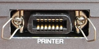
The micro ribbon or miniature ribbonconnector is a common type of electrical connector for a variety of applications, such as in computer and telecommunications equipment having many contacts.

<span class="mw-page-title-main">IDC (electrical connector)</span> Type of electrical connector

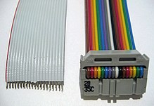
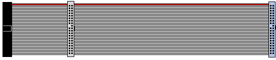
An insulation-displacement contact (IDC), also known as insulation-piercing contact (IPC), is an electrical connector designed to be connected to the conductor(s) of an insulated cable by a connection process which forces a selectively sharpened blade or blades through the insulation, bypassing the need to strip the conductors of insulation before connecting. When properly made, the connector blade cold-welds to the conductor, making a theoretically reliable gas-tight connection.

A SCSI connector is used to connect computer parts that use a system called SCSI to communicate with each other. Generally, two connectors, designated male and female, plug together to form a connection which allows two components, such as a computer and a disk drive, to communicate with each other. SCSI connectors can be electrical connectors or optical connectors. There have been a large variety of SCSI connectors in use at one time or another in the computer industry. Twenty-five years of evolution and three major revisions of the standards resulted in requirements for Parallel SCSI connectors that could handle an 8, 16 or 32 bit wide bus running at 5, 10 or 20 megatransfer/s, with conventional or differential signaling. Serial SCSI added another three transport types, each with one or more connector types. Manufacturers have frequently chosen connectors based on factors of size, cost, or convenience at the expense of compatibility.

Universal EXTension (UEXT) is a connector layout which includes power and three serial buses: Asynchronous, I2C, and SPI separately over 10 pins in a 2x5 layout. The connector layout was specified by Olimex Ltd and declared an open-project that is royalty-free in 2011, and was used in all their boards after 2004.

<span class="mw-page-title-main">Pin header</span> Type of simple electrical connector

A pin header is a form of electrical connector. A male pin header consists of one or more rows of metal pins molded into a plastic base, often 2.54 mm (0.1 in) apart, though available in many spacings. Male pin headers are cost-effective due to their simplicity. The female counterparts are sometimes known as female socket headers, though there are numerous naming variations of male and female connectors. Historically, headers have sometimes been called "Berg connectors" or "DuPont" connectors, but headers are manufactured by many companies.

<span class="mw-page-title-main">JST connector</span> Standard Japanese electrical connector

JST connectors are electrical connectors manufactured to the design standards originally developed by J.S.T. Mfg. Co.. JST manufactures numerous series (families) and pitches of connectors.

<span class="mw-page-title-main">Electronics prototyping</span>

In electronics, prototyping means building an actual circuit to a theoretical design to verify that it works, and to provide a physical platform for debugging it if it does not. The prototype is often constructed using techniques such as wire wrapping or using a breadboard, stripboard or perfboard, with the result being a circuit that is electrically identical to the design but not physically identical to the final product.

References

  1. Hunter Cable Assembly Ltd. "Ribbon-and-Flat-Cable-Assemblies-whitepaper.pdf" (PDF). white paper. Hunter Cable Assembly. Archived from the original (PDF) on 2016-03-03.
  2. Digital Systems Engineering, William J. Dally, John W. Poulton, page 52 "2.7.2.2 Ribbon cable"