
The D-subminiature or D-sub is a common type of electrical connector. They are named for their characteristic D-shaped metal shield. When they were introduced, D-subs were among the smallest connectors used on computer systems.
The D-subminiature or D-sub is a common type of electrical connector. They are named for their characteristic D-shaped metal shield. When they were introduced, D-subs were among the smallest connectors used on computer systems.
| Normal density | High density | Double density | |||
|---|---|---|---|---|---|
| Name | Pin layout | Name | Pin layout | Name | Pin layout |
| DA-15 | 8–7 | DA-26 | 9–9–8 | DA-31 | 10–11–10 |
| DB-25 | 13–12 | DB-44 | 15–15–14 | DB-52 | 17–18–17 |
| DC-37 | 19–18 | DC-62 | 21–21–20 | DC-79 | 26–27–26 |
| DD-50 | 17–16–17 | DD-78 | 20–19–20–19 | DD-100 | 26–25–24–25 |
| DE-9 | 5–4 | DE-15 | 5–5–5 | DE-19 | 6–7–6 |
| 19-pin [note 1] | 10–9 | 104-pin | 21–21–21–21–20 [1] [2] | ||
| 23-pin [note 1] | 12–11 | ||||
Note that the high density and double density classification here is the reverse of floppy disk nomenclature. Here, high density is intermediate, between nominal and double density. | |||||
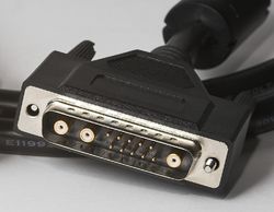
A D-sub contains two or more parallel rows of pins or sockets usually surrounded by a D-shaped metal shield, or shell, that provides mechanical support, ensures correct orientation, and may screen against electromagnetic interference. Calling that shield a shell (or D-shell) can be ambiguous, as the term shell is also short for the cable shell, or backshell. D-sub connectors have gender: parts with pin contacts are called male connectors or plugs, while those with socket contacts are called female connectors or sockets. The socket's shield fits tightly inside the plug's shield. Panel-mounted connectors usually have #4-40 UNC (as designated with the Unified Thread Standard) jackscrews that accept screws on the cable end connector cover that are used for locking the connectors together and offering mechanical strain relief, and can be tightened with a 3/16" (or 5mm) hex socket.
The hexagonal standoffs (4-40 bolts) at both sides of each connector have a threaded stud fastening the connectors to the metal panel. They also have threaded sockets to receive jackscrews on the cable shell, holding the plug and socket together.


Occasionally the nuts may be found on a cable end connector if it is expected to connect to another cable end (see the male DE-9 pictured). When screened cables are used, the shields are connected to the overall screens of the cables. This creates an electrically continuous screen covering the whole cable and connector system.
The D-sub series of connectors was introduced by Cannon in 1952. [3] Cannon's part-numbering system uses D as the prefix for the whole series, followed by one of A, B, C, D, or E denoting the shell size, followed by the number of pins or sockets, [4] followed by either P (plug or pins [5] ) or S (socket) denoting the gender of the part. Each shell size usually (see below for exceptions) corresponds to a certain number of pins or sockets: A with 15, B with 25, C with 37, D with 50, and E with 9. [6] For example, DB-25 denotes a D-sub with a 25-position shell size and a 25-position contact configuration. The contacts in each row of these connectors are spaced 326/3000 of an inch apart, or approximately 0.1087 inches (2.76 mm), and the rows are spaced 0.112 inches (2.84 mm) apart; the pins in the two rows are offset by half the distance between adjacent contacts in a row. [7] This spacing is called normal density. The suffixes M and F (for male and female) are sometimes used instead of the original P and S for plug and socket.


Later D-sub connectors added extra pins to the original shell sizes, and their names follow the same pattern. For example, the DE-15, usually found in VGA cables, has 15 pins in three rows, all surrounded by an E size shell. The pins are spaced at 0.090 inches (2.3 mm) horizontally and 0.078 inches (2.0 mm) vertically, [7] in what is called high density. The other connectors with the same pin spacing are the DA-26, DB-44, DC-62, DD-78 and 104-pin. They all have three rows of pins, except the DD-78 which has four, and the 104-pin which has five rows. [1] The double density series of D-sub connectors features even denser arrangements and consists of the DE-19, DA-31, DB-52, DC-79, and DD-100. These each have three rows of pins, except the DD-100, which has four.
The above naming pattern was not always followed. Because personal computers first used DB-25 connectors for their serial and parallel ports, when the PC serial port began to use 9-pin connectors, they were often mislabeled as DB-9 instead of DE-9 due to ignorance of the fact that B represented a much larger shell size. It is now common to see DE-9 connectors sold as "DB-9" connectors. DB-9 nearly always refers to a 9-pin connector with an E-size shell. The non-standard 23-pin D-sub connectors for external floppy drives and video output on most of the Amiga computers are usually labeled DB-23, even though their shell size is two pins smaller than ordinary DB sockets. Several computers also used a non-standard 19-pin D-sub connector, sometimes called DB-19, [8] including Macintosh (external floppy drive), Atari ST (external hard drive), and NeXT (Megapixel Display monitor [9] and laser printer).
Reflecting the same confusion of the letters DB with just D as mentioned above, high-density connectors are also often called DB-15HD (or even DB-15 or HD-15), DB-26HD (HD-26), DB-44HD, DB-62HD, and DB-78HD connectors, respectively, where HD stands for high density.
Cannon also produced combo D-subs with larger contacts in place of some of the normal contacts, for use for high-current, high-voltage, or co-axial inserts. The DB13W3 variant was commonly used for high-performance video connections; this variant provided 10 regular (#20) pins plus three coaxial contacts for the red, green, and blue video signals. Combo D-subs are currently manufactured in a broad range of configurations by other companies. [10] Some variants have current ratings up to 40 A; others are waterproof and meet IP67 standards.[ citation needed ]
A further family of connectors of similar appearance to the D-sub family uses names such as HD-50 and HD-68, and has a D-shaped shell about half the width of a DB-25. They are common in SCSI attachments.
The original D-sub connectors are now defined by an international standard, IEC 60807-3 / DIN 41652. The United States military also maintains another specification for D-subminiature connectors, the MIL-DTL-24308 standard. [7]

Smaller connectors have been derived from the D-sub including the microminiature D (micro-D) and nanominiature D (nano-D) which are trademarks of ITT Cannon. Micro-D is about half the length of a D-sub and Nano-D is about half the length of Micro-D. Their primary applications are in military and space-grade technology such as SpaceWire networks. The MIL-SPEC for Micro-D is MIL-DTL-83513 [11] and for Nano-D is MIL-DTL-32139. [12]

The widest application of D-subs is for RS-232 serial communications. RS-232 devices used the DB-25 as far back as the Bell 103 modem in 1967 (though the Teletype Model 33 was the most common ASCII RS-232 device, its signal interface was an internal Molex connector). The 1969 RS-232-C standard recommended the DB-25 female connectors for DTE and DCE devices, and male-to-male cables to connect them; this was codified in EIA-232D. The timesharing era from the mid-1960s to the early 1980s relied heavily on minicomputers, modems, printers, and video-display terminals connected by DB-25 cables.
As the EIA-232 standard improved, many of its defined signals became obsolete. Handshaking and secondary channel pins were not used, making a B-size connector unnecessarily large for two signal wires and ground. Vendors gradually moved away from the DB-25 to the more compact DE-9 for serial communications, and adopted standards other than EIA-232-D. The conventions for use of DB-25 eroded: the original IBM PC, and therefore many compatibles, used a DB-25 male connector at the device and a male-to-female cable to a modem, while using a female DB-25 connector as a parallel port (instead of the bulkier Centronics port found on the printer itself). Early Apple Macintosh models used DE-9 connectors for RS-422 multi-drop serial interfaces (which can operate as RS-232). Later Macintosh models use 8-pin miniature DIN connectors instead, while the IBM PC/AT switched to DE-9M connectors for serial communications.
Many uninterruptible power supply units have a DE-9F connector on them in order to signal to the attached computer via an RS-232 interface. Often these do not send data serially to the computer but instead use the handshaking control lines to indicate low battery, power failure, or other conditions. Such usage is not standardized between manufacturers and may require special cables.
DE-9 connectors were used for some Token Ring networks as well as other computer networks.

Originally in the 1980s Ethernet network interface cards or devices were connected using Attachment Unit Interface (AUI) cables to Medium Attachment Units that then connected to 10BASE5 and later 10BASE2 or 10BASE-T network cabling. The AUI cables used DA-15 connectors albeit with a sliding latch to lock the connectors together instead of the usual hex studs with threaded holes. The sliding latch was intended to be quicker to engage and disengage and to work in places where jackscrews could not be used for reasons of component shape.
In vehicles, DE-9 connectors are commonly used in Controller Area Networks (CAN): female connectors are on the bus while male connectors are on devices. [13]
A female 9-pin connector on an IBM compatible personal computer may be a digital RGBI video display output such as MDA, Hercules, CGA, or EGA (rarely VGA or others). Even though these all use the same DE-9 connector, the displays cannot all be interchanged and monitors or video interfaces may be damaged if connected to an incompatible device using the same connector. [14] [15] [16] [17] [18] [19]
| Adaptor | MDA | CGA | EGA | VGA (early DE-9 variant) |
|---|---|---|---|---|
| Pin 1 | Ground | Ground | Ground | + Analog red |
| Pin 2 | Ground | Ground | + Secondary red (intensity) | + Analog green |
| Pin 3 | + Red | + Red | + Analog blue | |
| Pin 4 | + Green | + Green | − Horizontal sync. (31.5 kHz) | |
| Pin 5 | + Blue | + Blue | ± Vertical sync. (70 / 60 Hz) | |
| Pin 6 | + Intensity | + Intensity | + Secondary green (intensity) | Red ground |
| Pin 7 | + Video | Reserved | + Secondary blue (intensity) | Green ground |
| Pin 8 | + Horizontal sync. (18.43 kHz) | + Horizontal sync. (15.7 kHz) | + Horizontal sync. (15.7 / 21.85 kHz) | Blue ground |
| Pin 9 | − Vertical sync. (50 Hz) | + Vertical sync. (60 Hz) | ± Vertical sync. (60 Hz) | Combined sync ground |

Later analog video (VGA and later) adapters generally replaced DE-9 connectors with DE-15 high-density sockets (though some early VGA devices still used DE-9 connectors). DE-15 connectors have the same shell size as DE-9 connectors (see above). The additional pins of the DE-15 VGA connector were used to add increasingly sophisticated monitor-sensing plug and play functionality.
Many Apple Macintosh models, beginning with the Macintosh II, used DA-15 sockets for analog RGB video out. These connectors had the same number of pins as the above DE-15 connectors, but used the more traditional pin size, pin spacing, and size shell of the DA-15 standard connector. "VGA adapters" (i.e. DA-15 to DE-15 dongles) were available but sometimes monitor-specific, or they needed DIP switch configuration, as the Macintosh's monitor sense pins [20] in particular were not identical with a VGA connector's DDC.
The earlier Apple IIGS used the same physical DA-15 connector for the same purpose but with an incompatible pinout. A digital (and thus also incompatible) RGB adapter for the Apple IIe also used a DA-15F. The Apple IIc used a DA-15F for an auxiliary video port which was not RGB but provided the necessary signals to derive RGB.

The 1977 Atari Video Computer System game console uses modified DE-9 connectors (male on the system, female on the cable) for its game controller connectors. The Atari joystick ports have bodies entirely of molded plastic without the metal shield, and they omit the pair of fastening screws. In the years following, various video game consoles and home computers adopted the same connector for their own game ports, though they were not all interoperable. The most common wiring supported five connections for discrete signals (five switches, for up, down, left, and right movement, and a fire button), plus one pair of 100 kΩ potentiometers, or paddles, for analog input. Some computers supported additional buttons, and on some computers additional devices, such as a computer mouse, a light pen, or a graphics tablet were also supported via the game port. Unlike the basic one-button digital joysticks and the basic paddles, such devices were not typically interchangeable between different systems.
Systems using the DE-9 connector for their game port include the TI-99/4A, [21] Atari 8-bit computers, Atari ST, Atari 7800, VIC-20, Commodore 64, Commodore 128, Amiga, Amstrad CPC (which employs daisy-chaining when connecting two Amstrad-specific joysticks), MSX, X68000, FM Towns, ColecoVision, SG-1000, Master System, Mega Drive/Genesis, and the 3DO Interactive Multiplayer.
The original ZX Spectrum lacks a built-in joystick connector of any kind but aftermarket interfaces provided the ability to connect DE-9 joysticks. Later Amstrad branded models included two DE-9 ports but used the proprietary ZX Interface 2 layout mapped to the number keys. NEC's home computers (e.g. PC-88, PC-98) also used DE-9 connectors for game controllers, depending on the sound card used.
The Fairchild Channel F System II [22] and Bally Astrocade [23] use DE-9 connectors for their detachable joystick as well. Both are incompatible with the Atari connector.
Many Apple II computers also use DE-9 connectors for joysticks, but they have a female port on the computer and a male on the controller, use analog rather than digital sticks, and the pinout is completely unlike that used on the aforementioned systems. DE-9 connectors were not used for game ports on the Macintosh, Apple III, IBM PC compatibles, or most game consoles outside the aforementioned examples. Sega switched to proprietary controller ports for the Saturn and Dreamcast.

DA-15S connectors are used for PC joystick connectors, where each DA-15 connector supports two joysticks each with two analog axes and two buttons. In other words, one DA-15S game adapter connector has 4 analog potentiometer inputs and 4 digital switch inputs. This interface is strictly input-only, though it does provide +5 V DC power. Some joysticks with more than two axes or more than two buttons use the signals designated for both joysticks. Conversely, Y-adapter cables are available that allow two separate joysticks to be connected to a single DA-15 game adapter port; if a joystick connected to one of these Y-adapters has more than two axes or buttons, only the first two of each will work.
The IBM DA-15 PC game connector has been modified to add a (usually MPU-401 compatible) MIDI interface, and this is often implemented in the game connectors on third-party sound cards, for example, the Sound Blaster line from Creative Labs. The standard straight game adapter connector (introduced by IBM) has three ground pins and four +5 V power pins, and the MIDI adaptation replaces one of the grounds and one of the +5 V pins, both on the bottom row of pins, with MIDI In and MIDI Out signal pins. (There is no MIDI Thru provided.) Creative Labs introduced this adaptation.[ citation needed ]
The Neo Geo AES game console also used the DA-15 connector, however, the pins are wired differently and it is therefore not compatible with the regular DA-15 PC game controllers. [24]
The Family Computer console had controllers that were hardwired but also included a DA-15 expansion port for additional peripherals. [25] Many clones of the hardware used a DA-15 which implemented a subset of the Famicom expansion port and were therefore compatible with some Famicom peripherals. Later clones switched to the cheaper DE-9 port. [26]
The Atari 5200 console also used a DA-15 instead of the DE-9 of its predecessor to facilitate the matrix for the keypad. [27] The Atari Falcon, Atari STe and Atari Jaguar used a DE-15. [28]
25-pin sockets on Macintosh computers are typically single-ended SCSI connectors, combining all signal returns into one contact (again in contrast to the Centronics C50 connector typically found on the peripheral, supplying a separate return contact for each signal), while older Sun hardware uses DD-50 connectors for Fast-SCSI equipment. As SCSI variants from Ultra2 onwards used differential signaling, the Macintosh DB-25 SCSI interface became obsolete.
D-subminiature connectors are often used in industrial products, the DA-15 version being commonly used on rotary and linear encoders.

The early Macintosh and late Apple II computers used a non-standard 19-pin D-sub for connecting external floppy disk drives. Atari also used this connector on their 16-bit computer range for attaching hard disk drives and the Atari laser printer, where it was known as both the ACSI (Atari Computer System Interface) port and the DMA bus port. The Commodore Amiga used an equally non-standard 23-pin version for both its video output (male) and its port for daisy-chaining up to three extra external floppy disk drives (female).
In professional audio, several connections use DB-25 connectors:
In broadcast and professional video, parallel digital is a digital video interface that uses DB-25 connectors, per the SMPTE 274M specification adopted in the late 1990s. The more common SMPTE 259M serial digital interface (SDI) uses BNC connectors for digital video signal transfer.
DC-37 connectors are commonly used in hospital facilities as an interface between hospital beds and nurse call systems, allowing for the connection and signaling of Nurse Call, Bed Exit, and Cord out including TV entertainment and lighting controls.[ citation needed ] The comparatively rare DC-37 connector was also found as the so-called "GeekPort" electronics experimentation breakout connector on the even rarer BeBox computer. [31]
DB-25 connectors are commonly used to carry analog signals for beam displacement and color control to laser projectors, as specified in the ISP-DB25 protocol published by the International Laser Display Association. [32]


There are many different methods used to attach wires to the contacts in D-sub connectors.
The wire wrap and IDC connections styles had to contend with incompatible pin spacing to the 0.05 in ribbon cable or 0.1 in proto board grid, especially for larger pin counts.