10BASE2

Last updated
10BASE2 cable showing the BNC connector end. BNC connector with 10BASE2 cable-92170.jpg
10BASE2 cable showing the BNC connector end.
10BASE2 cable with a BNC T-connector. BNC Tee connector, with Ethernet cable connected-92166.jpg
10BASE2 cable with a BNC T-connector.
10BASE2 cable end terminator. 10base2 terminator.png
10BASE2 cable end terminator.
EAD outlet Ead-outlet.jpg
EAD outlet
Different types of T-connectors, with AAUIs (an AUI variant specific to Apple computers) AAUI examples.jpg
Different types of T-connectors, with AAUIs (an AUI variant specific to Apple computers)

10BASE2 (also known as cheapernet, [1] thin Ethernet, thinnet, and thinwire) is a variant of Ethernet that uses thin coaxial cable terminated with BNC connectors to build a local area network.

Contents

During the mid to late 1980s, this was the dominant 10 Mbit/s Ethernet standard.

The use of twisted pair networks competed with 10BASE2's use of a single coaxial cable. In 1988, Ethernet over twisted pair was introduced, running at the same speed of 10 Mbit/s. In 1995, the Fast Ethernet standard upgraded the speed to 100 Mbit/s, and no such speed improvement was ever made for thinnet. By 2001, prices for Fast Ethernet cards had fallen to under $50. By 2003, Wi-Fi networking equipment was widely available and affordable.

Due to the immense demand for high-speed networking, the low cost of Category 5 cable, and the popularity of 802.11 wireless networks, both 10BASE2 and 10BASE5 have become increasingly obsolete, though devices still exist in some locations. [2] As of 2011, IEEE 802.3 has deprecated this standard for new installations. [3]

Name origination

The name 10BASE2 is derived from several characteristics of the physical medium. The 10 comes from the transmission speed of 10  Mbit/s. The BASE stands for baseband signaling, and the 2 for a maximum segment length approaching 200 m (the actual maximum length is 185 m).

Signal encoding

10 Mbit/s Ethernet uses Manchester coding. A binary zero is indicated by a low-to-high transition in the middle of the bit period and a binary one is indicated by a high-to-low transition in the middle of the bit period. Manchester coding allows the clock to be recovered from the signal. However, the additional transitions associated with it double the signal bandwidth.

Network design

10BASE2 coax cables have a maximum length of 185 metres (607 ft). The maximum practical number of nodes that can be connected to a 10BASE2 segment is limited to 30 [4] with a minimum distance of 0.5 metres (20 in) between devices. [5] In a 10BASE2 network, each stretch of cable is connected to the transceiver (which is usually built into the network adaptor) using a BNC T-connector, [lower-alpha 1] with one stretch connected to each female connector of the T. The T-connector must be plugged directly into the network adaptor with no cable in between.

As is the case with most other high-speed buses, Ethernet segments have to be terminated with a resistor at each end. Each end of the cable has a 50 ohm (Ω) resistor attached. Typically this resistor is built into a male BNC and attached to the last device on the bus. This is most commonly connected directly to the T-connector on a workstation. [lower-alpha 2] If termination is missing, or if there is a break in the cable, the AC signal on the bus is reflected, rather than dissipated, when it reaches the end. This reflected signal is indistinguishable from a collision, so no communication can take place.

Some terminators have a metallic chain attached to them for grounding purposes. The cable should be grounded only at one end. Grounding the terminators at both may produce a ground loop and can cause network outages or data corruption when swells of electricity traverse the coaxial cabling's outer shield.

When wiring a 10BASE2 network, special care has to be taken to ensure that cables are properly connected to all T-connectors. Bad contacts or shorts are especially difficult to diagnose. A failure at any point of the network cabling tends to prevent all communications. For this reason, 10BASE2 networks can be difficult to maintain and were often replaced by 10BASE-T networks, which (provided category 5 cable or better was used) also provided a good upgrade path to 100BASE-TX.

Comparisons to 10BASE-T

10BASE2 networks cannot generally be extended without breaking service temporarily for existing users and the presence of many joints in the cable also makes them very vulnerable to accidental or malicious disruption. There were proprietary systems that claimed to avoid these problems (e.g. SaferTap) but these never became widespread, possibly due to a lack of standardization. 10BASE-T can be extended by making a new connection to a hub. A fault in a one hub connection does not necessarily compromise other connections to the hub.

10BASE2 systems did have a number of advantages over 10BASE-T. No hub is required as with 10BASE-T, so the hardware cost was minimal, and wiring was particularly easy since only a single wire run is needed, which could be sourced from the nearest computer. These characteristics made 10BASE2 ideal for a small network of two or three machines, perhaps in a home where easily concealed wiring was an advantage. For a larger complex office network, the difficulties of tracing poor connections made it impractical. Unfortunately for 10BASE2, by the time multiple home computer networks became common, the format had already been practically superseded by 10BASE-T.

Comparisons to 10BASE5, use of AUI

10BASE2 uses RG-58A/U cable or similar for a maximum segment length of 185 m as opposed to the thicker RG-8-like cable used in 10BASE5 networks with a maximum length of 500 m. The RG-58 type wire used by 10BASE2 was inexpensive, smaller and much more flexible than the specialized RG-8 variant.

An Ethernet network interface controller (NIC) may include the 10BASE2 transceivers and thus directly provide a 10BASE2 BNC connector (that the T-connector plugs into), or it may offer an AUI connector that external transceivers (see Medium Attachment Unit) can connect to. These can be transceivers for 10BASE2, but also for 10BASE5 or 10BASE-T. Some NICs offer both BNC and AUI connectors, or other combinations including BNC and 10BASE-T. With multiple connections, only one connector is designed to be used at the same time.

See also

Notes

  1. Other connectors such as EAD sockets were promoted as a less error-prone alternative to BNC connectors.
  2. A few devices such as Digital's DEMPR and DESPR have a built-in terminator and so can only be used at one physical end of the cable run.

Related Research Articles

<span class="mw-page-title-main">Ethernet</span> Computer networking technology

Ethernet is a family of wired computer networking technologies commonly used in local area networks (LAN), metropolitan area networks (MAN) and wide area networks (WAN). It was commercially introduced in 1980 and first standardized in 1983 as IEEE 802.3. Ethernet has since been refined to support higher bit rates, a greater number of nodes, and longer link distances, but retains much backward compatibility. Over time, Ethernet has largely replaced competing wired LAN technologies such as Token Ring, FDDI and ARCNET.

100BaseVG is a 100 Mbit/s Ethernet standard specified to run over four pairs of Category 3 cable. It is also called 100VG-AnyLAN because it was defined to carry both Ethernet and Token Ring frame types.

<span class="mw-page-title-main">10BASE5</span> First commercially available variant of Ethernet

10BASE5 was the first commercially available variant of Ethernet. The technology was standardized in 1982 as IEEE 802.3. 10BASE5 uses a thick and stiff coaxial cable up to 500 meters (1,600 ft) in length. Up to 100 stations can be connected to the cable using vampire taps and share a single collision domain with 10 Mbit/s of bandwidth shared among them. The system is difficult to install and maintain.

<span class="mw-page-title-main">Ethernet over twisted pair</span> Ethernet physical layers using twisted-pair cables

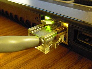
Ethernet over twisted-pair technologies use twisted-pair cables for the physical layer of an Ethernet computer network. They are a subset of all Ethernet physical layers.
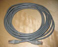
<span class="mw-page-title-main">Apple Attachment Unit Interface</span> Apple version of the standard Ethernet connection

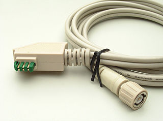
Apple Attachment Unit Interface (AAUI) is a mechanical re-design by Apple of the standard Attachment Unit Interface (AUI) used to connect computer equipment to Ethernet. The AUI was popular in the era before the dominance of 10BASE-T networking that started in the early 1990s; the AAUI was an attempt to make the connector much smaller and more user friendly, though the proprietary nature of the interface was also criticized.

<span class="mw-page-title-main">Fast Ethernet</span> Ethernet standards that carry data at the nominal rate of 100 Mbit/s

In computer networking, Fast Ethernet physical layers carry traffic at the nominal rate of 100 Mbit/s. The prior Ethernet speed was 10 Mbit/s. Of the Fast Ethernet physical layers, 100BASE-TX is by far the most common.

<span class="mw-page-title-main">ARCNET</span>

Attached Resource Computer NETwork is a communications protocol for local area networks. ARCNET was the first widely available networking system for microcomputers; it became popular in the 1980s for office automation tasks. It was later applied to embedded systems where certain features of the protocol are especially useful.

StarLAN was the first IEEE 802.3 standard for Ethernet over twisted pair wiring. It was standardized by the IEEE Standards Association as 802.3e in 1986, as the 1BASE5 version of Ethernet. The StarLAN Task Force was chaired by Bob Galin.

A network segment is a portion of a computer network. The nature and extent of a segment depends on the nature of the network and the device or devices used to interconnect end stations.

<span class="mw-page-title-main">Attachment Unit Interface</span> Physical and logical interface defined in the original Ethernet standard

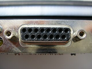
The Attachment Unit Interface (AUI) is a physical and logical interface defined in the original IEEE 802.3 standard for 10BASE5 Ethernet and the previous DIX standard. The physical interface consists of a 15-pin D-subminiature connection that provides a path between an Ethernet node's physical signaling and the Medium Attachment Unit (MAU), sometimes also known as a transceiver. An AUI cable may be up to 50 metres long, although frequently the cable is omitted altogether and the MAU and medium access controller MAC are directly attached to one another. On Ethernet implementations without separate MAU and MAC, the AUI is omitted.

<span class="mw-page-title-main">Electrical termination</span> Transmission line impedance matching

In electronics, electrical termination is the practice of ending a transmission line with a device that matches the characteristic impedance of the line. Termination prevents signals from reflecting off the end of the transmission line. Reflections at the ends of unterminated transmission lines cause distortion, which can produce ambiguous digital signal levels and misoperation of digital systems. Reflections in analog signal systems cause such effects as video ghosting, or power loss in radio transmitter transmission lines.

<span class="mw-page-title-main">Medium Attachment Unit</span>

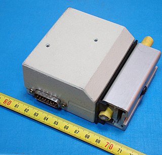
A Medium Attachment Unit (MAU) is a transceiver which converts signals on an Ethernet cable to and from Attachment Unit Interface (AUI) signals.

<span class="mw-page-title-main">Ethernet hub</span> Device for interconnecting Ethernet devices

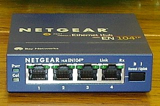
An Ethernet hub, active hub, network hub, repeater hub, multiport repeater, or simply hub is a network hardware device for connecting multiple Ethernet devices together and making them act as a single network segment. It has multiple input/output (I/O) ports, in which a signal introduced at the input of any port appears at the output of every port except the original incoming. A hub works at the physical layer. A repeater hub also participates in collision detection, forwarding a jam signal to all ports if it detects a collision. In addition to standard 8P8C ("RJ45") ports, some hubs may also come with a BNC or an Attachment Unit Interface (AUI) connector to allow connection to legacy 10BASE2 or 10BASE5 network segments.

<span class="mw-page-title-main">Medium-dependent interface</span> Interface between a network device and the data link it communicates over

A medium-dependent interface (MDI) describes the interface in a computer network from a physical-layer implementation to the physical medium used to carry the transmission. Ethernet over twisted pair also defines a medium-dependent interface – crossover (MDI-X) interface. Auto–MDI-X ports on newer network interfaces detect if the connection would require a crossover and automatically choose the MDI or MDI-X configuration to complement the other end of the link.

<span class="mw-page-title-main">Ethernet physical layer</span> Electrical or optical properties between network devices

The physical-layer specifications of the Ethernet family of computer network standards are published by the Institute of Electrical and Electronics Engineers (IEEE), which defines the electrical or optical properties and the transfer speed of the physical connection between a device and the network or between network devices. It is complemented by the MAC layer and the logical link layer. An implementation of a specific physical layer is commonly referred to as PHY.

<span class="mw-page-title-main">EAD socket</span>

An EAD socket was a network connection socket used in the early 1990s. They are now considered obsolete.

Ethernet over Coax (EoC) is a family of technologies that supports the transmission of Ethernet frames over coaxial cable. The Institute of Electrical and Electronics Engineers (IEEE) maintains all official Ethernet standards in the IEEE 802 family.

<span class="mw-page-title-main">Accton Technology Corporation</span> Taiwanese electronics company

Accton Technology Corporation is a Taiwanese company in the electronics industry that primarily engages in the development and manufacture of networking and communication solutions, as an original equipment manufacturer (OEM) or original design manufacturer (ODM) partner.

The 5-4-3 rule, also referred to as the IEEE way, is a design guideline for Ethernet computer networks covering the number of repeaters and segments on shared-medium Ethernet backbones in a tree topology. It means that in a collision domain there should be at most 5 segments tied together with 4 repeaters, with up to 3 mixing segments. Link segments can be 10BASE-T, 10BASE-FL or 10BASE-FB. This rule is also designated the 5-4-3-2-1 rule with there being two link segments and one collision domain.

Physical media refers to the physical materials that are used to store or transmit information in data communications. These physical media are generally physical objects made of materials such as copper or glass. They can be touched and felt, and have physical properties such as weight and color. For a number of years, copper and glass were the only media used in computer networking.

References

  1. Alex Djenguerian (June 1986). "Ethernet/Cheapernet Physical Layer Made Easy with DP8391/92" (PDF). National Semiconductor. Archived (PDF) from the original on 2022-10-09. Retrieved 2019-08-13.
  2. "L-com Introduces Commercial-Grade Thinnet (10Base-2) and Thicknet (10Base-5) Converters for Legacy Installs". L-com, Inc. 2012-06-11. Retrieved 2012-07-01.
  3. IEEE 802.3-2012 10. Medium attachment unit and baseband medium specifications, type 10BASE2
  4. IEEE 802.3 10.7.2.2 MAU placement
  5. IEEE 802.3 10.7.2.1 Cable sectioning