Related Research Articles

10BASE2 is a variant of Ethernet that uses thin coaxial cable terminated with BNC connectors to build a local area network.
In electrical engineering, a transmission line is a specialized cable or other structure designed to conduct electromagnetic waves in a contained manner. The term applies when the conductors are long enough that the wave nature of the transmission must be taken into account. This applies especially to radio-frequency engineering because the short wavelengths means wave phenomena arise over very short distances. However, the theory of transmission lines was historically developed to explain phenomena on very long telegraph lines, especially submarine telegraph cables.

Coaxial cable, or coax is a type of electrical cable consisting of an inner conductor surrounded by a concentric conducting shield, with the two separated by a dielectric ; many coaxial cables also have a protective outer sheath or jacket. The term "coaxial" refers to the inner conductor and the outer shield sharing a geometric axis.
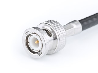
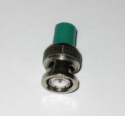
The BNC connector is a miniature quick connect/disconnect radio frequency connector used for coaxial cable.

A balun is an electrical device that converts between a balanced signal and an unbalanced signal. A balun can take many forms and may include devices that also transform impedances but need not do so. Transformer baluns can also be used to connect lines of differing impedance. Sometimes, in the case of transformer baluns, they use magnetic coupling but need not do so. Common-mode chokes are also used as baluns and work by eliminating, rather than ignoring, common mode signals.
Twin-lead cable is a two-conductor flat cable used as a balanced transmission line to carry radio frequency (RF) signals. It is constructed of two stranded or solid copper or copper-clad steel wires, held a precise distance apart by a plastic ribbon. The uniform spacing of the wires is the key to the cable's function as a transmission line; any abrupt changes in spacing would reflect some of the signal back toward the source. The plastic also covers and insulates the wires. It is available with several different values of characteristic impedance, the most common type is 300 ohm.
In electronics, electrical termination is the practice of ending a transmission line with a device that matches the characteristic impedance of the line. Termination prevents signals from reflecting off the end of the transmission line. Reflections at the ends of unterminated transmission lines cause distortion which can produce ambiguous digital signal levels and mis-operation of digital systems. Reflections in analog signal systems cause such effects as video ghosting, or power loss in radio transmitter transmission lines.

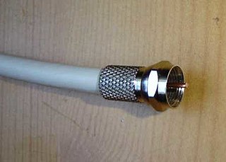
The F connector is a coaxial RF connector commonly used for "over the air" terrestrial television, cable television and universally for satellite television and cable modems, usually with RG-6/U cable or with RG-59/U cable.

SMA connectors are semi-precision coaxial RF connectors developed in the 1960s as a minimal connector interface for coaxial cable with a screw-type coupling mechanism. The connector has a 50 Ω impedance. SMA was originally designed for use from DC (0 Hz) to 12 GHz, however this has been extended over time and variants are available to 18 GHZ and 26.5 GHz. There are also mechanically compatible connectors such as the K-connector which operate upto 40 GHz. The SMA connector most commonly used in microwave systems, hand-held radio and mobile telephone antennas, and more recently with WiFi antenna systems and USB software-defined radio dongles. It is also commonly used in radio astronomy, particularly at higher frequencies (5 GHz+).
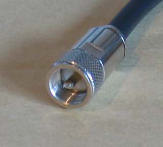
The UHF connector is a name for a threaded RF connector. The connector design was invented in the 1930s for use in the radio industry, and is a shielded form of the "banana plug". It is a widely used standard connector for HF transmission lines on full-sized radio equipment, with BNC connectors predominating for smaller, hand-held equipment.
RG-59/U is a specific type of coaxial cable, often used for low-power video and RF signal connections. The cable has a characteristic impedance of 75 ohms, and a capacitance of around 20pF/ft (60pF/m). The 75 ohm impedance matches a dipole antenna in free space. RG was originally a unit indicator for bulk radio frequency (RF) cable in the U.S. military's Joint Electronics Type Designation System. The suffix /U means for general utility use. The number 59 was assigned sequentially. The RG unit indicator is no longer part of the JETDS system (MIL-STD-196E) and cable sold today under the RG-59 label does not necessarily meet military specifications.

The Musa connector is a type of coaxial ("coax") connector, originally developed for the manual switching of radio signals. It has a characteristic impedance of 75 Ω, and was adopted for use in the emerging television broadcast industry.

A test probe is a physical device used to connect electronic test equipment to a device under test (DUT). Test probes range from very simple, robust devices to complex probes that are sophisticated, expensive, and fragile. Specific types include test prods, oscilloscope probes and current probes. A test probe is often supplied as a test lead, which includes the probe, cable and terminating connector.

RG-6/U is a common type of coaxial cable used in a wide variety of residential and commercial applications. An RG-6/U coaxial cable has a characteristic impedance of 75 ohms. The term, RG-6, is generic and is applied to a wide variety of cable designs, which differ from one another in shielding characteristics, center conductor composition, dielectric type and jacket type. RG was originally a unit indicator for bulk radio frequency (RF) cable in the U.S. military's Joint Electronics Type Designation System. The suffix /U means for general utility use. The number was assigned sequentially. The RG unit indicator is no longer part of the JETDS system (MIL-STD-196E) and cable sold today under the RG-6 label is unlikely to meet military specifications. In practice, the term RG-6 is generally used to refer to coaxial cables with an 18 AWG center conductor and 75 ohm characteristic impedance.
A bias tee is a three-port network used for setting the DC bias point of some electronic components without disturbing other components. The bias tee is a diplexer. The low-frequency port is used to set the bias; the high-frequency port passes the radio-frequency signals but blocks the biasing levels; the combined port connects to the device, which sees both the bias and RF. It is called a tee because the 3 ports are often arranged in the shape of a T.
Nominal impedance in electrical engineering and audio engineering refers to the approximate designed impedance of an electrical circuit or device. The term is applied in a number of different fields, most often being encountered in respect of:

The DIN 1.0/2.3 connector is a RF connector used for coaxial cable at microwave frequencies. They were introduced in the 1990s for telecommunication applications. They are available in 50 Ω and 75 Ω impedance and are compatible with the most widely used cable sizes. It has a push/pull lock and release feature. The DIN 1.0/2.3 is ideally suited to applications where space limitation is a factor. In broadcasting applications the 75 Ω version is used for Serial Digital Interface video data up to maximum frequency of 4 GHz. The 50 Ω connector can be used to a maximum of 10 GHz.

The 7-16 DIN connector or 7/16 is a 50 Ω threaded RF connector used to join coaxial cables. It is among the most widely used high power RF connectors in cellular network antenna systems. Originally popular in Europe, it has gained widespread use in the US and elsewhere. It is not to be confused with the similar-sounding EIA flange adaptors which are referred to by the outer diameter in fractions of an inch. The 7–16 DIN connector is also defined by an international standard, IEC 61169-4. It out performs other non-flange options, such as N connectors or BNC connectors, when it comes to interference and intermodulation rejection or higher power handling at RF frequencies.
Wi-Fi over Coax is a technology for extending and distributing Wi-Fi signals via coaxial cables. As an in-building wireless solution, Wi-Fi over Coax can make use of existing or new cabling with native impedance of 50 Ω shared by a Wi-Fi access point, cabling run, and antenna. Coaxial cables with characteristic impedance of 75 Ω, such as RG-6 cables used for in-building television distribution, can also be used by incorporating impedance converters. As part of a distributed antenna system, Wi-Fi over Coax can connect multiple floors of a home or office via power dividers and zoned antennas either passively or via amplifiers, potentially eliminating the need for multiple access points.
References
- ↑ "RG Coaxial and Triaxial Reference Guide" (PDF). Archived from the original (PDF) on 2012-05-11. Retrieved 2012-06-24.
- ↑ Coaxial Cable Loss and Dynamics by Benton County ARES/RACES. Archived from the original on 20 Feb. 2020
| This electronics-related article is a stub. You can help Wikipedia by expanding it. |