Micro ribbon 36-pin female, such as on printers and on some computers, particularly industrial equipment and early (pre-1980s) personal computers.Mini-Centronics 36-pin male connector (top) with Micro ribbon 36-pin male Centronics connector (bottom)The Apple II Parallel Printer Port connected to the printer via a folded ribbon cable; one end connected to the connector at the top of the card, and the other end had a 36-pin Centronics connector.
In computing, a parallel port is a type of interface found on early computers (personal and otherwise) for connecting peripherals. The name refers to the way the data is sent; parallel ports send multiple bits of data at once (parallel communication), as opposed to serial communication, in which bits are sent one at a time. To do this, parallel ports require multiple data lines in their cables and port connectors and tend to be larger than contemporary serial ports, which only require one data line.
There are many types of parallel ports, but the term has become most closely associated with the printer port or Centronics port found on most personal computers from the 1970s through the 2000s. It was an industry de facto standard for many years, and was finally standardized as IEEE 1284 in the late 1990s, which defined the Enhanced Parallel Port (EPP) and Extended Capability Port (ECP) bi-directional versions. Today, the parallel port interface is virtually non-existent in new computers because of the rise of Universal Serial Bus (USB) devices, along with network printing using Ethernet and Wi-Fi connected printers.
The parallel port interface was originally known as the Parallel Printer Adapter on IBM PC-compatible computers. It was primarily designed to operate printers that used IBM's eight-bit extended ASCIIcharacter set to print text, but could also be used to adapt other peripherals. Graphical printers, along with a host of other devices, have been designed to communicate with the system.
History
Centronics
An Wang, Robert Howard and Prentice Robinson began development of a low-cost printer at Centronics, a subsidiary of Wang Laboratories that produced specialty computer terminals. The printer used the dot matrix printing principle, with a print head consisting of a vertical row of seven metal pins connected to solenoids. When power was applied to the solenoids, the pin was pushed forward to strike the paper and leave a dot. To make a complete character glyph, the print head would receive power to specified pins to create a single vertical pattern, then the print head would move to the right by a small amount, and the process repeated. On their original design, a typical glyph was printed as a matrix seven high and five wide, while the "A" models used a print head with 9 pins and formed glyphs that were 9 by 7.[2]
This left the problem of sending the ASCII data to the printer. While a serial port does so with the minimum of pins and wires, it requires the device to buffer up the data as it arrives bit by bit and turn it back into multi-bit values. A parallel port makes this simpler; the entire ASCII value is presented on the pins in complete form. In addition to the eight data pins, the system also needed various control pins as well as electrical grounds. Wang happened to have a surplus stock of 20,000 Amphenol 36-pin micro ribbon connectors that were originally used for one of their early calculators. The interface only required 21 of these pins, the rest were grounded or not connected. The connector has become so closely associated with Centronics that it is now popularly known as the "Centronics connector".[3]
The Centronics Model 101 printer, featuring this connector, was released in 1970.[3] The host sent ASCII characters to the printer using seven of eight data pins, pulling them high to +5V to represent a 1. When the data was ready, the host pulled the STROBE pin low, to 0 V. The printer responded by pulling the BUSY line high, printing the character, and then returning BUSY to low again. The host could then send another character. Control characters in the data caused other actions, like the CR or EOF. The host could also have the printer automatically start a new line by pulling the AUTOFEED line high, and keeping it there. The host had to carefully watch the BUSY line to ensure it did not feed data to the printer too rapidly, especially given variable-time operations like a paper feed.[2][4]
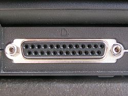
The printer side of the interface quickly became an industry de facto standard, but manufacturers used various connectors on the system side, so a variety of cables were required. For example, NCR used the 36-pin micro ribbon connector on both ends of the connection, early VAX systems used a DC-37 connector, Texas Instruments used a 25-pin card edge connector and Data General used a 50-pin micro ribbon connector. When IBM implemented the parallel interface on the IBM PC, they used the DB-25F connector at the PC-end of the interface, creating the now familiar parallel cable with a DB25M at one end and a 36-pin micro ribbon connector at the other.
In theory, the Centronics port could transfer data as rapidly as 75,000 characters per second. This was far faster than the printer, which averaged about 160 characters per second, meaning the port spent much of its time idle. The performance was defined by how rapidly the host could respond to the printer's BUSY signal asking for more data. To improve performance, printers began incorporating buffers so the host could send them data more rapidly, in bursts. This not only reduced (or eliminated) delays due to latency waiting for the next character to arrive from the host, but also freed the host to perform other operations without causing a loss of performance. Performance was further improved by using the buffer to store several lines and then printing in both directions, eliminating the delay while the print head returned to the left side of the page. Such changes more than doubled the performance of an otherwise unchanged printer, as was the case on Centronics models like the 102 and 308.[4]
IBM
IBM released the IBM Personal Computer in 1981 and included a variant of the Centronics interface— only IBM logo printers (rebranded from Epson) could be used with the IBM PC.[5] IBM standardized the parallel cable with a DB25F connector on the PC side and the 36-pin Centronics connector on the printer side. Vendors soon released printers compatible with both standard Centronics and the IBM implementation.
The original IBM parallel printer adapter for the IBM PC of 1981 was designed to support limited bidirectionality, with 8 lines of data output and 4 lines of data input.[citation needed] This allowed the port to be used for other purposes, not just output to a printer. This was accomplished by allowing the data lines to be written to by devices on either end of the cable, which required the ports on the host to be bidirectional. This feature saw little use, and was removed in later revisions of the hardware. Years later, in 1987, IBM reintroduced the bidirectional interface with its IBM PS/2 series, where it could be enabled or disabled for compatibility with applications hardwired not to expect a printer port to be bidirectional.
Bi-Tronics
As the printer market expanded, new types of printing mechanisms appeared. These often supported new features and error conditions that could not be represented on the existing port's relatively few status pins. While the IBM solution could support this, it was not trivial to implement and was not at that time being supported. This led to the Bi-Tronics system, introduced by HP on their LaserJet 4Si in April 1993.[6] This used four existing status pins, ERROR, SELECT, PE and BUSY to represent a nibble, using two transfers to send an 8-bit value. Bi-Tronics mode, now known as nibble mode, was indicated by the host pulling the SELECT line high, and data was transferred when the host toggles the AUTOFEED low. Other changes in the handshaking protocols improved performance, reaching 400,000 cps to the printer, and about 50,000 cps back to the host.[7] A major advantage of the Bi-Tronics system is that it can be driven entirely in software in the host, and uses otherwise unmodified hardware - all the pins used for data transfer back to the host were already printer-to-host lines.
EPP and ECP
The introduction of new devices like scanners and multi-function printers demanded much more performance than either the Bi-Tronics or IBM style backchannels could handle. Two other standards have become more popular for these purposes. The Enhanced Parallel Port (EPP), originally defined by Zenith Electronics, is similar to IBM's byte mode in concept, but changes details of the handshaking to allow up to 2 MB/s.[8] The Extended Capability Port (ECP) is essentially an entirely new port in the same physical housing that also adds direct memory access based on ISA and run-length encoding to compress the data, which is especially useful when transferring simple images like faxes or black-and-white scanned images. ECP offers performance up to 2.5 MB/s (20 Mbps) in both directions.[9]
All of these enhancements are collected as part of the IEEE 1284 standard. The first release in 1994 included original Centronics mode ("compatibility mode"), nibble and byte modes, as well as a change to the handshaking that was already widely used; the original Centronics implementation called for the BUSY lead to toggle with each change on any line of data (busy-by-line), whereas IEEE 1284 calls for BUSY to toggle with each received character (busy-by-character). This reduces the number of BUSY toggles and the resulting interruptions on both sides. A 1997 update standardized the printer status codes. In 2000, the EPP and ECP modes were moved into the standard, as well as several connector and cable styles, and a method for daisy chaining up to eight devices from a single port.[9]
Some host systems or print servers may use a strobe signal with a relatively low voltage output or a fast toggle. Any of these issues might cause no or intermittent printing, missing or repeated characters or garbage printing. Some printer models may have a switch or setting to set busy by character; others may require a handshake adapter.[citation needed]
Dataproducts
Dataproducts introduced a very different implementation of the parallel interface for their printers. It used a DC-37 connector on the host side and a 50 pin connector on the printer side—either a DD-50 (sometimes incorrectly referred to as a "DB50") or the block shaped M-50 connector; the M-50 was also referred to as Winchester.[10][11] Dataproducts parallel was available in a short-line for connections up to 50 feet (15m) and a long-line version using differential signaling for connections to 500 feet (150m). The Dataproducts interface was found on many mainframe systems up through the 1990s, and many printer manufacturers offered the Dataproducts interface as an option.
A wide variety of devices were eventually designed to operate on a parallel port. Most devices were uni-directional (one-way) devices, only meant to respond to information sent from the PC. However, some devices such as Zip drives were able to operate in bi-directional mode. Printers also eventually took up the bi-directional system, allowing various status report information to be sent.
Historical uses
HP C4381A CD-Writer Plus 7200 Series, showing parallel ports to connect between a printer and the computer.
Before the advent of USB, the parallel interface was adapted to access a number of peripheral devices other than printers. One early use of the parallel port was for dongles used as hardware keys which were supplied with application software as a form of software copy protection. Other uses included optical disc drives such as CD readers and writers, Zip drives, scanners, tape drives,[12] external modems, gamepads, and joysticks. Some of the earliest portable MP3 players required a parallel port connection for transferring songs to the device.[13] Adapters were available to run SCSI devices via parallel. Other devices such as EPROM programmers and hardware controllers could be connected via the parallel port.
Interfaces
Most PC-compatible systems in the 1980s and 1990s had one to three ports, with communication interfaces defined like this:
Logical parallel port 1: I/O port 0x3BC to 0x3BF, IRQ 7 (usually in monochrome graphics adapters)
Logical parallel port 2: I/O port 0x378 to 0x37F, IRQ 7 (dedicated IO cards or using a controller built into the mainboard)
Logical parallel port 3: I/O port 0x278 to 0x27F, IRQ 5 (dedicated IO cards or using a controller built into the mainboard)
If no printer port is present at 0x3BC, the second port in the row (0x378) becomes logical parallel port 1 and 0x278 becomes logical parallel port 2 for the BIOS. Sometimes, printer ports are jumpered to share an interrupt despite having their own IO addresses (i.e. only one can be used interrupt-driven at a time). In some cases, the BIOS supports a fourth printer port as well, but the base address for it differs significantly between vendors. Since the reserved entry for a fourth logical printer port in the BIOS Data Area (BDA) is shared with other uses on PS/2 machines and with S3 compatible graphics cards, it typically requires special drivers in most environments. Under DR-DOS 7.02 the BIOS port assignments can be changed and overridden using the LPT1, LPT2, LPT3 (and optionally LPT4) CONFIG.SYS directives.
Access
DOS-based systems make the logical parallel ports detected by the BIOS available under device names such as LPT1, LPT2 or LPT3 (corresponding with logical parallel port 1, 2, and 3, respectively). These names derive from terms like Line Print Terminal, Local Print Terminal (both abbreviated as LPT), or Line Printer. A similar naming convention was used on ITS, DEC systems, as well as in CP/M and 86-DOS (LST).
In DOS, the parallel printers could be accessed directly on the command line. For example, the command "TYPE C:\AUTOEXEC.BAT > LPT1:" would redirect the contents of the AUTOEXEC.BAT file to the printer port. A PRN device was also available as an alias for LPT1. Some operating systems (like Multiuser DOS) allow to change this fixed assignment by different means. Some DOS versions use resident driver extensions provided by MODE, or users can change the mapping internally via a CONFIG.SYSPRN=n directive (as under DR-DOS 7.02 and higher). DR-DOS 7.02 also provides optional built-in support for LPT4 if the underlying BIOS supports it.
PRN, along with CON, AUX and a few others are invalid file and directory names in DOS and Windows, even on Windows XP and later. This set of invalid file and directory names also affects Windows 95 and 98, which had an MS-DOS device in path name vulnerability in which it causes the computer to crash if the user types "C:\CON\CON", "C:\PRN\PRN" or "C:\AUX\AUX" in the Windows Explorer address bar or via the Run command.[citation needed]Microsoft has since released a patch to fix this issue, however new installations of Windows 95 and 98 are not patched with this fix and will still have this issue.
A special "PRINT" command also existed to achieve the same effect. Microsoft Windows still refers to the ports in this manner in many cases, though this is often fairly hidden.
In SCO UNIX and Linux, the first parallel port is available via the filesystem as /dev/lp0. Linux IDE devices can use a paride (parallel port IDE) driver.[14]
Notable consumer products
Accton Etherpocket-SP parallel port ethernet adaptor (circa 1990, DOS drivers). Supports both coax and 10 Base-T. Supplementary power is drawn from a PS/2 port passthrough cable.
For consumers, USB and computer networks have replaced the parallel printer port, for connections both to printers and to other devices.
Many manufacturers of personal computers and laptops consider parallel to be a legacy port and no longer include the parallel interface. Smaller machines have less room for large parallel port connectors. USB-to-parallel adapters are available that can make parallel-only printers work with USB-only systems. There are PCI (and PCI-express) cards that provide parallel ports. There are also some print servers that provide an interface to parallel ports through a network. USB-to-EPP chips can also allow other non-printer devices to continue to work on modern computers without a parallel port.[16]
For electronics hobbyists the parallel port is still often the easiest way to connect to an external circuit board. It is faster than the other common legacy port (serial port), requires no serial-to-parallel converter, and requires far less interface logic and software than a USB target interface. However, Microsoft operating systems later than Windows 95/98 prevent user programs from directly writing to or reading from the LPT without additional software (kernel extensions).[17]
CNC Milling Machines also often make use of the parallel port to directly control the machine's motors and attachments, especially with LinuxCNC OS.
IBM PC implementation
Port addresses
Traditionally IBM PC systems have allocated their first three parallel ports according to the configuration in the table below (if all three printer ports exist).
If there is an unused slot, the port addresses of the others are moved up. (For example, if a port at 0x3BC does not exist, the port at 0x378 will then become the first logical parallel port.)[18] The base address 0x3BC is typically supported by printer ports on MDA and Hercules display adapters, whereas printer ports provided by the mainboard chipset or add-on cards rarely allow to be configured to this base address. Therefore, in absence of a monochrome display adapter, a common assignment for the first logical parallel port (and therefore also for the corresponding LPT1 DOS device driver) today is 0x378, even though the default is still 0x3BC (and would be selected by the BIOS if it detects a printer port at this address). The IRQ lines are typically configurable in the hardware as well. Assigning the same interrupt to more than one printer port should be avoided and will typically cause one of the corresponding ports to work in polled mode only. The port addresses assigned to slot can be determined by reading the BIOS Data Area (BDA) at 0000h:0408h.
Bit-to-pin mapping for the Standard Parallel Port (SPP):
In versions of Windows that did not use the Windows NT kernel (as well as DOS and some other operating systems), programs could access the parallel port with simple outportb() and inportb() subroutine commands. In operating systems such as Windows NT and Unix (NetBSD, FreeBSD, Solaris, 386BSD, etc.), the microprocessor is operated in a different security ring, and access to the parallel port is prohibited, unless using the required driver. This improves security and arbitration of device contention. On Linux, inb() and outb() can be used when a process is run as root and an ioperm() command is used to allow access to its base address; alternatively, ppdev allows shared access and can be used from userspace if the appropriate permissions are set.
The cross-platform library for parallel port access, libieee1284, also is available on many Linux distributions and provides an abstract interface to the parallel ports of the system. Access is handled in an open-claim-release-close sequence, which allows for concurrent access in userspace.
Pinouts
The older parallel printer ports had an 8-bit data bus and four pins for control output (Strobe, Linefeed, Initialize, and Select In), and five more for control input (ACK, Busy, Select, Error, and Paper Out). Its data transfer speed is at 150 kB/s.[1] It is possible for a parallel port to have a speed of 300 KB/s.[19]
The newer EPPs (Enhanced Parallel Ports) have an 8-bit data bus, and the same control pins as the normal parallel printer port. Newer ports reach speeds of up to 2 MB/s.[20][bettersourceneeded]
For peripheral side, example parallel port interface chips: PPC34C60 (SMSC) and W91284PIC (Warp Nine)
For USB-printer purpose, example USB chips: PL-2305 (Prolific) and CH341 (QinHeng)
References
12James, Kevin. PC interfacing and data acquisition: techniques for measurement, instrumentation and control. Oxford; Boston: Newnes, 2000. ISBN9780750646246. p. 256
12Webster, Edward C. (2000). Print Unchained: Fifty Years of Digital Printing: A Saga of Invention and Enterprise. West Dover, VT: DRA of Vermont. ISBN0-9702617-0-5.
This page is based on this Wikipedia article Text is available under the CC BY-SA 4.0 license; additional terms may apply. Images, videos and audio are available under their respective licenses.