The Color Graphics Adapter (CGA), originally also called the Color/Graphics Adapter or IBM Color/Graphics Monitor Adapter,[1] introduced in 1981, was IBM's first color graphics card for the IBM PC and established a de factocomputer display standard.
The original IBM CGA graphics card was built around the Motorola 6845 display controller,[2] came with 16kilobytes of video memory built in, and featured several graphics and text modes. The highest display resolution of any mode was 640 × 200, and the highest color depth supported was 4-bit (16colors).
The CGA card could be connected either to a direct-drive CRT monitor using a 4-bit digital (TTL) RGBI interface, such as the IBM 5153 color display, or to an NTSC-compatible television or composite videomonitor via an RCA connector.[3] The RCA connector provided only baseband video, so to connect the CGA card to a television set without a composite video input required a separate RF modulator.[1]
IBM produced the 5153 Personal Computer Color Display for use with the CGA, but this was not available at release[4] and would not be released until March 1983.[5]
Although IBM's own color display was not available, customers could either use the composite output (with an RF modulator if needed), or the direct-drive output with available third-party monitors that supported the RGBI format and scan rate. Some third-party displays lacked the intensity input, reducing the number of available colors to eight,[4] and many also lacked IBM's unique circuitry which rendered the dark-yellow color as brown, so any software that used brown would be displayed incorrectly.
160 × 100 in 16 colors, chosen from a 16-color palette, utilizing a specific configuration of the 80 × 25 text mode.
This used 4 bits per pixel, with a total memory use of (160× 100× 4)/ 8= 8 kilobytes.
320 × 200 in 4 colors, chosen from 3 fixed palettes, with high- and low-intensity variants, with color 1 chosen from a 16-color palette.
This used 2 bits per pixel, with a total memory use of (320× 200× 2)/ 8= 16 kilobytes.
640 × 200 in 2 colors, one black, one chosen from a 16-color palette.
This used 1 bit per pixel, with a total memory use of (640× 200)/ 8= 16 kilobytes.
Some software achieved greater color depth by utilizing artifact color when connected to a composite monitor.
Text modes:
40 × 25 with 8 × 8 pixel font (effective resolution of 320 × 200)
80 × 25 with 8 × 8 pixel font (effective resolution of 640 × 200)
IBM intended that CGA be compatible with a home television set. The 40 × 25 text and 320 × 200 graphics modes are usable with a television, and the 80 × 25 text and 640 × 200 graphics modes are intended for a monitor.[2]
PCPaint in 320×200 3rd palette low intensity, showing a typical low resolution interface. Note the use of dithering to overcome the CGA palette limitations
SimCity in 640×200 monochrome. Note the use of dithering to simulate gray tones and non-square pixel ratio that deforms the fonts
CGA uses a 4-bit RGBI 16-color gamut, but not all colors are available at all times, depending on which graphics mode is being used. In the medium- and high-resolution modes, colors are stored at a lower bit depth and selected by fixed palette indexes, not direct selection from the full 16-color palette.
When four bits are used (for low-resolution mode, or for programming color registers) they are arranged according to the RGBI color model:[8]
The lower three bits represent red, green, and blue color components
The fourth "intensifier" bit, when set, increases the brightness of all three color components (red, green, and blue).[9]
CGA palette internal bit arrangement (4-bit RGBI)[8]
Color
I
R
G
B
Color
I
R
G
B
Black
0
0
0
0
Gray 2
1
0
0
0
Blue
0
0
0
1
Light Blue
1
0
0
1
Green
0
0
1
0
Light Green
1
0
1
0
Cyan
0
0
1
1
Light Cyan
1
0
1
1
Red
0
1
0
0
Light Red
1
1
0
0
Magenta
0
1
0
1
Light Magenta
1
1
0
1
Brown
0
1
1
0
Light Yellow
1
1
1
0
Gray 1
0
1
1
1
White
1
1
1
1
These four colour bits are then interpreted internally by the monitor, or converted to NTSC colours (see below).
With an RGBI monitor
When using a direct-drive monitor, the four color bits are output directly to the DE-9 connector at the back of the card.
Within the monitor, the four signals are interpreted to drive the red, green and blue color guns. With respect to the RGBI color model described above, the monitor would translate the digital four-bit color number to some seven distinctive analog voltages in the range from 0.0 to 1.0 for each gun.[10]
dark yellow
6
#AAAA00
Color 6 is treated specially; normally, color 6 would become dark yellow, as seen to the right, but in order to achieve a more pleasing brown tone, special circuitry in most RGBI monitors, starting with the IBM 5153 color display,[11] makes an exception for color 6 and changes its hue from dark yellow to brown by reducing the analogue green signal's amplitude. The exact amount of reduction differed between monitor models: the original IBM 5153 Personal Computer Color Display reduces the green signal's amplitude by about one third,[12] while the IBM 5154 Enhanced Color Display internally converts all 4-bit RGBI color numbers to 6-bit ECD color numbers,[8] which amounts to halving the green signal's amplitude. The Tandy CM-2,[13] CM-4[14] and CM-11[15] monitors provide a potentiometer labelled "BROWN ADJ." to adjust the amount of green signal reduction.
This "RGBI with tweaked brown" palette was retained as the default palette of later PC graphics standards such as EGA and VGA, which can select colors from much larger gamuts, but default to these until reprogrammed.
Later video cards/monitors in CGA emulation modes would approximate the colors with the following formula:
red := 2/3×(colorNumber & 4)/4 + 1/3×(colorNumber & 8)/8 green := 2/3×(colorNumber & 2)/2 + 1/3×(colorNumber & 8)/8 blue := 2/3×(colorNumber & 1)/1 + 1/3×(colorNumber & 8)/8 if (color == 6) green := green * 2/3
Note: Color hex values shown are 8-bit RGB equivalents, internally CGA is 4-bit RGBI
With a composite color monitor/television set
CGA's 16 colors when using the NTSC output (post-1983 card revision)
For the composite output, these four-bit color numbers are encoded by the CGA's onboard hardware into an NTSC-compatible signal fed to the card's RCA output jack. For cost reasons, this is not done using an RGB-to-YIQ converter as called for by the NTSC standard, but by a series of flip-flops and delay lines.[16][17]
Consequently, the hues seen are lacking in purity; notably, both cyan and yellow have a greenish tint, and color 6 again looks dark yellow instead of brown.[18]
The relative luminances of the colors produced by the composite color-generating circuit differ between CGA revisions: they are identical for colors 1-6 and 9-14 with early CGAs produced until 1983,[19] and are different for later CGAs due to the addition of additional resistors.[20]
CGA offers four BIOS text modes (Modes 0 to 3, called alphanumeric or A/N modes in IBM's documentation). In these modes, individual pixels on the screen cannot be addressed directly. Instead, the screen is divided into a grid of character cells, each displaying a character defined in one of two bitmap fonts, "normal" and "thin", included in the card's ROM. The fonts are fixed and cannot be modified or selected from software, only by a jumper on the board itself.
Fonts are stored as bitmaps at a color depth of 1-bit, with a "1" representing the character and a "0" representing the background. These colors can be chosen independently, for each character on the screen, from the full 16-color CGA palette. The character set is defined by hardware code page437.
The font bitmap data is only available to the card itself, it cannot be read by the CPU. In graphics modes, text output by the BIOS operates by copying text from the font ROM bit-by-bit to video memory.
40× 25 mode
BIOS Modes 0 and 1 are both 40 columns by 25 rows text modes, with each character a pattern of 8 × 8 dots. The effective screen resolution in this mode is 320 × 200 pixels (a pixel aspect ratio of 1:1.2.) The card has sufficient video RAM for eight different text pages in this mode.
The difference between these two modes can only be seen on a composite monitor, where mode 0 disables the color burst, making all text appear in grayscale. Mode 1 enables the color burst, allowing for color. Mode 0 and Mode 1 are functionally identical on RGB monitors and on later adapters that emulate CGA without supporting composite color output.
80× 25 mode
BIOS Modes 2 and 3 select 80 columns by 25 rows text modes, with each character still an 8 × 8 dot pattern, but displayed at a higher scan rate. The effective screen resolution of this mode is 640 × 200 pixels. In this mode, the card has enough video RAM for four different text pages.
As with the 40-column text modes, Mode 2 disables the color burst in the composite signal and Mode 3 enables it.
Textmode color
Each character cell stored four bits for foreground and background color. However, in the card's default configuration, the fourth bit of the background color does not set intensity, but sets the blink attribute for the cell. All characters on the screen with this bit set will periodically blink, meaning their foreground color will be changed to their background color so the character becomes invisible. All characters blink in unison.
By setting a hardware register, the blink feature can be disabled, restoring access to high-intensity background colors.
All blinking characters on the screen blink in sync. The blinking attribute effect is enabled by default and the high-intensity background effect is disabled; disabling blinking is the only way to freely choose the latter eight-color indexes (8-15) for the background color.
Notably, the GW-BASIC and Microsoft QBASIC programming languages included with MS-DOS supported all the text modes of the CGA with full color control, but did not provide a normal means through the BASIC language to switch the CGA from blink mode to 16-background-color mode. This was still possible however by directly programming the hardware registers using the OUT statement of the BASIC language.
Standard graphics modes
CGA offers graphics modes at three resolutions: 160 × 100, 320 × 200 and 640 × 200. In all modes every pixel on the screen can be set directly, but the color depth for the higher modes does not permit selecting freely from the full 16-color palette.
320× 200
In the medium-resolution 320 × 200 modes (Modes 4 and 5), each pixel is two bits, which select colors from a four-color palette. In mode 4, there are two palettes, and in mode 5 there is a single palette.
CGA hardware palettes on a RGBI monitor
#
Mode 4
Mode 5
Palette 0
Palette 1
low intensity
high intensity
low intensity
high intensity
low intensity
high intensity
0
0 – background
0 – background
0 – background
0 – background
0 – background
0 – background
1
2 – green
10 – light green
3 – cyan
11 – light cyan
3 – cyan
11 – light cyan
2
4 – red
12 – light red
5 – magenta
13 – light magenta
4 – red
12 – light red
3
6 – brown
14 – yellow
7 – light gray
15 – white
7 – light gray
15 – white
Several choices can be made by programming hardware registers. First, the selected palette. Second, the intensity – which is defined for the entire screen, not on a per-pixel basis. Third, color 0 (the "background" color) can be set to any of the 16 colors.
The specific BIOS graphics mode influences which palettes are available. BIOS Mode 4 offers two palettes: green/red/brown and cyan/magenta/white.
As with the text modes 0 and 2, Mode 5 disables the color burst to allow colors to appear in grayscale on composite monitor. However, unlike the text modes, this also affects the colors displayed on an RGBI monitor, altering them to the cyan/red/white palette seen above. This palette is not documented by IBM, but was used in some software.
640× 200
In the high-resolution 640 × 200 mode (Mode 6), each pixel is one bit, providing two colors which can be chosen from the 16-color palette by programming hardware registers.
In this mode, the video picture is stored as a simple bitmap, with one bit per pixel setting the color to "foreground" or "background". By default the colors are black and bright white, but the foreground color can be changed to any entry in the 16-color CGA palette. The background color cannot be changed from black on an original IBM CGA card.
This mode disables the composite color burst signal by default. The BIOS does not provide an option to turn the color burst on in 640× 200 mode, and the user must write directly to the mode control register to enable it.
Further graphics modes and tweaks
A number of official and unofficial features exist that can be exploited to achieve special effects.
In 320 × 200 graphics mode, the background color (which also affects the border color), which defaults to black on mode initialization, can be changed to any of the other 15 colors of the CGA palette. This allows for some variation, as well as flashing effects, as the background color can be changed without having to redraw the screen (i.e. without changing the contents of the video RAM).
In text mode, the border color (displayed outside the regular display area and including the overscan area) can be changed from the default black to any of the other 15colors.
Through precision timing, it is possible to switch to another palette while the video is being output, allowing the use of any one of the six palettes per scanline. An example of this is California Games,[21] when run on a stock 4.77MHz 8088. Running on a faster computer does not produce the effect, as the method the programmers used to switch palettes at predetermined locations is extremely sensitive to machine speed. The same can be done with the background color, as is used to create the river and road in Frogger.[22] Another documented example of the technique is in Atarisoft's port of Jungle Hunt to the PC.
Additional colors can be approximated using dithering.
Using palette 0 at low intensity and dark blue as the background color provides the three primary RGB colors, as well as brown.
Some of these above tweaks can be combined. Examples can be found in several games.[23]
160× 100 16 color mode
A single big "pixel" in 160 × 100 mode. This is the two top rows of half of character 221. Note the eight constituent non-square pixels and the 1:1.2 pixel aspect ratio.Title screen of PakuPaku, a Pac-Man clone that uses 160 × 100 mode
Technically, this mode is not a graphics mode, but a tweak of the 80 × 25 text mode.[24] The character cell height register is changed to display only two lines per character cell instead of the normal eight lines. This quadruples the number of text rows displayed from 25 to 100. These "tightly squeezed" text characters are not full characters. The system only displays their top two lines of pixels (eight each) before moving on to the next row.
Character 221
221 with blue text and red background color
221 with red text and blue background color.
Character 222
Character 221 of the CGA character set consists of a box occupying the entire left half of the character matrix. (Character 222 consists of a box occupying the entire right half.)
Because each character can be assigned different foreground and background colors, it can be colored (for example) blue on the left (foreground color) and bright red on the right (background color). This can be reversed by swapping the foreground and background colors.
Using either character 221 or 222, each half of each truncated character cell can thus be treated as an individual pixel—making 160 horizontal pixels available per line. Thus, 160 × 100 pixels at 16colors, with a pixel aspect ratio of 1:1.2, are possible.
Although a roundabout way of achieving a 16-color graphics display, this works quite well and the mode is even mentioned (although not explained) in IBM's official hardware documentation.[25] This mode was used as early as 1983 on the game Moon Bugs.[26][27][28]
More detail can be achieved in this mode by using other characters, combining ASCII art with the aforesaid technique. This was explored by Macrocom, Inc on two games: Icon: Quest for the Ring (released in 1984) and The Seven Spirits of Ra (released in 1987).[28][29][30]
The same text cell height reduction technique can also be used with the 40 × 25 text mode, yielding a resolution of 80 × 100 and a pixel aspect ratio of ~1.67:1.
Using the composite output instead of an RGBI monitor produced lower-quality video, due to NTSC's inferior separation between luminance and chrominance.[31] This is especially a problem with 80-column text:[32]
80-column text on RGB (left) vs. composite monitor (right)
For this reason, each of the text and graphics modes has a duplicate mode which disables the composite colorburst, resulting in a black-and-white picture, but also eliminating color bleeding to produce a sharper picture. On RGBI monitors, the two versions of each mode are usually identical, with the exception of the 320 × 200 graphics mode, where the "monochrome" version produces a third palette.
Extended artifact colors
Programmers discovered that this flaw could be turned into an asset, as distinct patterns of high-resolution dots would turn into consistent areas of solid colors, thus allowing the display of completely new artifact colors. Both the standard 320 × 200 four-color and the 640 × 200 color-on-black graphics modes could be used with this technique.
Internal operation
Direct colors are the normal 16 colors as described above under "The CGA color palette".
Artifact colors are seen because the composite monitor's NTSC chroma decoder misinterprets some of the luminance information as color. By carefully placing pixels in appropriate patterns, a programmer can produce specific cross-color artifacts yielding a desired new color; either from purely black-and-white pixels in 640 × 200 mode, or resulting from a combination of direct and artifact colors in 320 × 200 mode, as seen on the following pictures:
CGA composite artifact color generation: pixels as displayed on a RGBI (left) or composite (right) monitor.
640 × 200
320 × 200 palette 0
320 × 200 palette 1
Thus, with the choice between 320 × 200 vs. 640 × 200 mode, the choice between the two palettes, and one freely-selectable color (the background in 320 × 200 modes and the foreground in 640 × 200 mode), it is possible to use many different sets of artifact colors, making for a total gamut of over 100colors.
1024 colors in composite mode
Later demonstrations by enthusiasts have increased the maximum number of colors the CGA can display at the same time to 1024.[33][34] This technique involves a text mode tweak which quadruples the number of text rows. Certain ASCII characters such as U and ‼ are then used to produce the necessary patterns, which result in non-dithered images with an effective resolution of 80 × 100 on a composite monitor.[33]
160 cycles of the NTSC color clock occur during each line's output, so in 40-column mode each pixel occupies half a cycle and in 80-column mode each pixel uses a quarter of a cycle. Limiting the character display to the upper one or two scanlines, and taking advantage of the pixel arrangement in certain characters of the codepage 437, it is possible to display up to 1024 colors.[33] This technique was used in the demo8088 MPH.[34]
Availability and caveats
The 320 × 200 variant of this technique (see above) is how the standard BIOS-supported graphics mode looks on a composite color monitor. The 640 × 200 variant, however, requires modifying a bit (color burst disable) directly in the CGA's hardware registers. As a result, it is usually referred to as a separate "mode".
Being completely dependent on the NTSC encoding/decoding process, composite color artifacting is not available on an RGBI monitor, nor is it emulated by EGA, VGA or contemporary graphics adapters.
The modern, games-centric PC emulator DOSBox supports a CGA mode, which can emulate a composite monitor's color artifacting. Both 640 × 200 composite mode and the more complex 320 × 200 variant are supported.
Resolution and usage
Composite artifacting, whether used intentionally or as an unwanted artifact, reduces the effective horizontal resolution to a maximum of 160 pixels, more for black-on-white or white-on-black text, without changing the vertical resolution. The resulting composite video display with "artifacted" colors is sometimes described as a 160 × 200/ 16-color "mode", though technically it was a technique using a standard mode.
The low resolution of this composite color artifacting method led to it being used almost exclusively in games. Many high-profile titles offered graphics optimized for composite color monitors. Ultima II, the first game in the game series to be ported to IBM PC, used CGA composite graphics. King's Quest I also offered 16-color graphics on the PC, PCjr and Tandy 1000, but provided a 'RGB mode' at the title screen which would utilize only the ordinary CGA graphics mode, limited to 4 colors.
Examples of CGA games on RGBI and composite monitors
Microsoft Decathlon. Top: game in composite mode; bottom: game in RGB mode; left: with RGB monitor; right: with composite monitor.
King's Quest. Top: game in composite mode; bottom: game in RGB mode; left: with RGB monitor; right: with composite monitor.
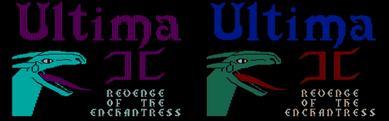
Ultima II. Left: with RGB monitor; right: with composite monitor.
Limitations, bugs and errata
Video timing on the CGA is provided by the Motorola 6845 video controller. This integrated circuit was originally designed only for character-based alphanumeric (text) displays and can address a maximum of 128 character rows.
To realize graphics modes with 200 scanlines on the CGA, the MC6845 is programmed with 100 character rows per picture and two scanlines per character row. Because the video memory address output by the MC6845 is identical for each scanline within a character row, the CGA must use the MC6845's "row address" output (i.e. the scanline within the character row) as an additional address bit to fetch raster data from video memory.[35]
This implies that unless the size of a single scanline's raster data is a power of two, raster data cannot be laid out continuously in video memory. Instead, graphics modes on the CGA store the even-numbered scanlines contiguously in memory, followed by a second block of odd-numbered scanlines starting at video memory position 8,192. This arrangement results in additional overhead in graphics modes for software that manipulates video memory.
Even though the MC6845 video controller can provide the timing for interlaced video, the CGA's circuitry aligns the synchronization signals in such a way that scanning is always progressive. Consequently, it is impossible to double the vertical resolution to 400 scanlines using a standard 15kHz monitor.
The higher bandwidth used by 80-column text mode results in random short horizontal lines appearing onscreen (known as "snow") if a program writes directly to video memory during screen drawing. The BIOS avoids the problem by only accessing the memory during horizontal retrace, or by temporarily turning off the output during scrolling. While this causes the display to flicker, IBM decided that doing so was better than snow.[2] The "snow" problem does not occur on any other video adapter, or on most CGA clones.
In the 80-column text mode, the pixel clock frequency is doubled, and all synchronization signals are output for twice the number of clock cycles in order to last for their proper duration. The composite output's color burst signal circuit is an exception: because it still outputs the same number of cycles, now at the doubled clock rate, the color burst signal produced is too short for most monitors, yielding no or unstable color. Hence, IBM documentation lists the 80-column text mode as a "feature" only for RGBI and black-and-white composite monitors.[36] Stable color can still be achieved by setting the border color to brown, which happens to produce a phase identical to the correct color burst signal and serves as a substitute for it.
Dual-head support
The CGA was released alongside the IBM MDA, and can be installed alongside the MDA in the same computer. A command included with PC DOS permits switching the display output between the CGA and MDA cards.[37] Some programs like Lotus 1-2-3[38] and AutoCAD support using both displays concurrently.
Software support
CGA was widely supported in PC software up until the early 1990s. Some of the software that supported the board was:
Visi On (an early GUI, used the 640x200 monochrome mode)
Windows 3.0 (and earlier versions, supported the 640x200 monochrome mode[39])
BYTE in January 1982 described the output from CGA as "very good—slightly better than color graphics on existing microcomputers".[4]PC Magazine disagreed, reporting in June 1983 that "the IBM monochrome display is absolutely beautiful for text and wonderfully easy on the eyes, but is limited to simple character graphics. Text quality on displays connected to the color/graphics adapter ... is at best of medium quality and is conducive to eyestrain over the long haul".[40]
In a retrospective commentary, Next Generation also took a negative view on the CGA, stating: "Even for the time (early 1980s), these graphics were terrible, paling in comparison to other color machines available on the market."[41]
CGA had several competitors:
For business and word processing use, IBM provided the Monochrome Display Adapter (MDA) at the same time as CGA. MDA was much more popular than CGA at first.[42] Since a great many PCs were sold to businesses, the sharp, high-resolution monochrome text was more desirable for running applications.
In 1982, the non-IBM Hercules Graphics Card (HGC) was introduced, the first third-party video card for the PC. In addition to an MDA-compatible text mode, it offered a monochrome graphics mode with a resolution of 720 × 348 pixels, higher than the CGA.
Also in 1982 the Plantronics Colorplus board was introduced, with twice the memory of a standard CGA board (32k, compared to 16k). The additional memory can be used in graphics modes to double the color depth, giving two additional graphics modes—16 colors at 320 × 200 resolution, or 4 colors at 640 × 200 resolution.
The IBM PCjr (1984) and compatible Tandy 1000 (1985) featured onboard "extended CGA" video hardware that extended video RAM beyond 16kB, allowing 16 colors at 320 × 200 resolution and four colors at 640 × 200 resolution. Because the Tandy 1000 long outlived the PCjr, the video modes became known as "Tandy Graphics Adapter" or "TGA", and were very popular for games during the 1980s. Similar but less widely used was the Plantronics Colorplus.
In 1984, IBM also introduced the Professional Graphics Controller, a high-end graphics solution intended for e.g. CAD applications. It was mostly backwards compatible with CGA. The PGC did not see widespread adoption due to its $4,000 price tag, and was discontinued in 1987.
Other alternatives:
Paradise Systems introduced in 1984 the first successful CGA-compatible card for MDA monitors. It displayed CGA's 16 colors in shades of monochrome. Because it was hardware-compatible with CGA, the Paradise card did not need special software support or additional drivers.[43]
Another extension in some CGA-compatible chipsets (including those in the Olivetti M24 / AT&T 6300, the DECVAXmate, and some Compaq and Toshiba portables) is a doubled vertical resolution. This gives a higher quality 8 × 16 text display and an additional 640 × 400 graphics mode.
The CGA card was succeeded in the consumer space by IBM's Enhanced Graphics Adapter (EGA) card, which supports most of CGA's modes and adds an additional resolution (640 × 350) as well as a software-selectable palette of 16 colors out of 64 in both text and graphics modes.
Specifications
DE-9 connector for RGBI monitor
DE-9 connector seen when looking at the back of a PC
The Color Graphics Adapter uses a standard DE-9 connector for direct-drive video (to an RGBI monitor). The connector on the card is female and the one on the monitor cable is male.
CGA DE-9 connector pin assignments
Pin
Function
1
Ground
2
Ground
3
Red
4
Green
5
Blue
6
Intensity
7
Reserved
8
Horizontal Sync
9
Vertical Sync
CGA TTL signal
Type
Digital, TTL
Resolution
640× 200, 320× 200
H-freq
15699.8Hz (14.318181MHz/8/114)
V-freq
59.923Hz (H-freq/262)
Colors
16
RCA connector for composite monitor or television
Back of a CGA Video Adapter board, with the RCA composite output connector visible on the right
The Color Graphics Adapter uses a standard RCA connector for connection to an NTSC-compatible television or composite videomonitor.[3] The connector on the card is female and the one on the monitor cable is male.
↑The color brown, represented by R=1, G=1, B=0, I=0, is an exception; whereas a straight interpretation of these bit values would resolve this color as dark yellow, the intensity of the green component is reduced, to produce brown, for only this one 4-bit value. See this page for details. This special RGBI interpretation for brown is performed in the monitor; the IBM 5153 monitor designed for the CGA performs it, but some early third-party monitors did not.
↑Analog Devices. "Low Cost RGB to NTSC/PAL Encoder with Luma Trap Port"(PDF). p.15. Retrieved 2020-10-18. The sharp transitions from black to white ... contain frequency components ..., and those in the chroma band create cross chrominance.
This page is based on this Wikipedia article Text is available under the CC BY-SA 4.0 license; additional terms may apply. Images, videos and audio are available under their respective licenses.