Parallel SCSI

Last updated

Amphenol-50 SCSI plug Centronics 50 SCSI connector.JPG
Amphenol-50 SCSI plug

Parallel SCSI (formally, SCSI Parallel Interface, or SPI) is the earliest of the interface implementations in the SCSI family. SPI is a parallel bus; there is one set of electrical connections stretching from one end of the SCSI bus to the other. A SCSI device attaches to the bus but does not interrupt it. Both ends of the bus must be terminated.

Contents

SCSI is a peer-to-peer peripheral interface. Every device attaches to the SCSI bus in a similar manner. Depending on the version, up to 8 or 16 devices can be attached to a single bus. There can be multiple hosts and multiple peripheral devices but there should be at least one host. The SCSI protocol defines communication from host to host, host to a peripheral device, and peripheral device to a peripheral device. [lower-alpha 1] The Symbios Logic 53C810 chip is an example of a PCI host interface that can act as a SCSI target.

SCSI-1 and SCSI-2 have the option of parity bit error checking. Starting with SCSI-U160 (part of SCSI-3) all commands and data are error checked by a cyclic redundancy check.

History

The first two formal SCSI standards, SCSI-1 and SCSI-2, described parallel SCSI. The SCSI-3 standard then split the framework into separate layers which allowed the introduction of other data interfaces beyond parallel SCSI. The original SCSI-1 version of the parallel bus was 8 bits wide (plus a ninth parity bit). The SCSI-2 standard allowed for faster operation (10 MHz) and wider buses (16-bit or 32-bit). The 16-bit option became the most popular.

At 10 MHz with a bus width of 16 bits it is possible to achieve a data rate of 20 MB/s. Subsequent extensions to the SCSI standard allowed for faster speeds: 20 MHz, 40 MHz, 80 MHz, 160 MHz and finally 320 MHz. At 320 MHz x 16 bits there is a theoretical maximum peak data rate of 640 MB/s.

Due to the technical constraints of a parallel bus system, SCSI has since evolved into faster serial interfaces, mainly Serial Attached SCSI and Fibre Channel. The iSCSI protocol doesn't describe a data interface but uses any IP network, usually run over Ethernet.

Standards

Parallel SCSI is not a single standard, but a suite of closely related standards. There are a dozen SCSI interface names, most with ambiguous wording (like Fast SCSI, Fast Wide SCSI, Ultra SCSI, and Ultra Wide SCSI); three SCSI standards, each of which has a collection of modular, optional features; several different connector types; and three different types of voltage signaling. The leading SCSI card manufacturer, Adaptec, has manufactured over 100 varieties of SCSI cards over the years. In actual practice, many experienced technicians simply refer to SCSI devices by their bus bandwidth (i.e., SCSI 320 or SCSI 160) in Megabytes per second.

As of 2003, there have only been three SCSI standards: SCSI-1, SCSI-2, and SCSI-3. All SCSI standards have been modular, defining various capabilities that manufacturers can include or not. Individual vendors and the SCSI Trade Association have given names to specific combinations of capabilities. For example, the term Ultra SCSI is not defined anywhere in the standard, but is used to refer to SCSI implementations that signal at twice the rate of Fast SCSI. Such a signaling rate is not compliant with SCSI-2 but is one option allowed by SCSI-3. Similarly, no version of the standard requires low-voltage-differential (LVD) signaling, but products called Ultra-2 SCSI include this capability. This terminology is helpful to consumers because Ultra-2 SCSI device has a better-defined set of capabilities than simply identifying it as SCSI-3.

Starting with SCSI-3, the SCSI standard has been maintained as a loose collection of standards, each defining a certain piece of the SCSI architecture, and bound together by the SCSI Architectural Model. This change divorces SCSI's various interfaces from the SCSI command set, allowing devices that support SCSI commands to use any interface (including ones not otherwise specified by T10), and also allowing the interfaces that are defined by T10 to be used in alternate manners.

No version of the standard has ever specified what kind of SCSI connector should be used. See § External connectors.

Comparison table

InterfaceAlternative namesSpecification document [upper-alpha 1] ConnectorWidth (bits)Clock (MHz)MaximumElectrical
ThroughputLength (m)Devices [upper-alpha 2] Impedance (Ω)Voltage (V)
(MB/s)(Mbit/s)Single ended [upper-alpha 3] LVD [upper-alpha 4] HVD
SCSI-1Narrow SCSISCSI-1 (1986) [upper-alpha 5] IDC50; Amphenol C50855406N/A258 SE 90 ± 6 [2] SE 5
Fast SCSISCSI-2 (1994)IDC50; Amphenol C5081010803N/A258 SE 90 ± 6 [2] SE 5 HVD ≥5
Fast-Wide SCSIWide SCSISCSI-2;
SPI-5 (INCITS 367-2003)
68-pin1610201603N/A2516 SE 90 ± 6 [2] SE 5 HVD ≥5
Ultra SCSIFast-20SPI-5 (INCITS 367-2003)IDC50820201601.5N/A258 SE 90 ± 6 [2] SE 5 HVD ≥5
3N/AN/A4
Ultra Wide SCSISPI-5 (INCITS 367-2003)68-pin162040320N/AN/A2516 SE 90 ± 6 [2] SE 5 HVD ≥5
1.5N/AN/A8
3N/AN/A4
Ultra2 SCSIFast-40SPI-5 (INCITS 367-2003)50-pin84040320N/A12258 LVD 125 ± 10 [2] LVD 1.2 HVD ≥5
Ultra2 Wide SCSISPI-5 (INCITS 367-2003)68-pin;80-pin(SCA/SCA-2)164080640N/A122516 LVD 125 ± 10 [2] LVD 1.2 HVD ≥5
Ultra3 SCSIUltra-160; Fast-80 wideSPI-5 (INCITS 367-2003)68-pin;80-pin(SCA/SCA-2)1640 DDR 1601280N/A12N/A16 LVD 125 ± 10 [2] LVD 1.2
Ultra-320 SCSIUltra-4; Fast-160SPI-5 (INCITS 367-2003)68-pin;80-pin(SCA/SCA-2)1680 DDR3202560N/A12N/A16 LVD 125 ± 10 [2] LVD 1.2
Ultra-640 SCSI [upper-alpha 6] [upper-alpha 7] Ultra-5; Fast-320SPI-5 (INCITS 367-2003)68-pin;80-pin16160 DDR6405120N/A10N/A16 LVD 125 ± 10LVD 1.2
  1. Specifications are maintained by the T10 subcommittee of the International Committee for Information Technology Standards.
  2. Including any host adapters (i.e., computers count as a device).
  3. For daisy-chain designs, length of bus, from end to end; for point-to-point, length of a single link.
  4. LVD cabling may be up to 25 m when only a single device is attached to the host adapter, 20 m for Ultra-640.
  5. The SCSI-1 specification has been withdrawn and is superseded by SCSI-2. The SCSI-3 SPI specification has been withdrawn and is superseded by SPI-2. The SCSI-3 SPI-3 and SPI-4 specifications have been withdrawn and are superseded by SPI-5. [1]
  6. Ultra-640 substantially increases the requirements for cabling and backplanes, hampering a smooth transition. [3]
  7. Ultra-640 was specified but no devices were produced. [4]

SCSI-1

NCR 53C94 SCSI-1 controller in PLCC-84 package Ncr 53c94 scsi asic.jpeg
NCR 53C94 SCSI-1 controller in PLCC-84 package

The original SCSI standard, SCSI-1, was derived from the Shugart Associates System Interface (SASI) and formally adopted in 1986 by ANSI. SCSI-1 features an 8-bit parallel bus (with parity), running asynchronously at 3.5 MB/s, or 5 MB/s in synchronous mode, and a maximum bus cable length of 6 metres (20 ft), significantly longer than the 18 inches (0.46 m) limit of the ATA interface also popular at the time. A rarely-seen variation on the original standard featured high-voltage differential signaling and supported a maximum cable length of 25 metres (82 ft).

SCSI-2

AMD 53CF94 SCSI-2 controller in PLCC-84 package 53CF94 SCSI-2 ASIC.gif
AMD 53CF94 SCSI-2 controller in PLCC-84 package

SCSI-2 was introduced in 1994 and gave rise to the Fast SCSI and Wide SCSI variants. Fast SCSI doubled the maximum transfer rate to 10 MB/s while retaining the same 50-pin cables, while Wide SCSI doubled the bus width to 16 bits on top of that to reach a maximum transfer rate of 20 MB/s, using new 68-pin cables. However, these improvements came at the cost of reducing the maximum cable length to three meters. SCSI-2 also specified a 32-bit version of Wide SCSI, which used two 16-bit cables per bus. The 32-bit implementation was largely ignored because it was deemed expensive and unnecessary, and was officially retired in SCSI-3.

SCSI-2 expanded the command set with the Common Command Set (CCS) for better support of devices other than disk drives, introduced command queueing (up to 256 commands per device) and tightened up the requirements on some features that were optional in SCSI-1; parity was now mandatory and the host adapter was required to provide termination power in order to support active termination. SCSI-1 devices would generally remain compatible while simply ignoring the new features. [5]

A high-voltage differential (HVD) mode that was incompatible with standard single-ended (SE) was introduced to accommodate longer bus lengths.

SCSI-3

Before Adaptec and later the SCSI Trade Association codified the terminology, the first parallel SCSI devices that exceeded the SCSI-2 capabilities were simply designated SCSI-3. These devices, also known as Ultra SCSI [6] or Fast-20 SCSI, [7] were introduced in 1996. SCSI-3 itself is not as much a single document as a collection of various standards that have received updates at different points in time.

The bus speed was doubled again to 20 MB/s for narrow (8-bit) systems and 40 MB/s for wide (16-bit). The maximum cable length remained 3 meters but single-ended Ultra SCSI developed an undeserved reputation for extreme sensitivity to cable length and condition (faulty cables, connectors or terminators were often to blame for instability problems).

Unlike previous SCSI standards, SCSI-3 (Fast-20 speed) requires active termination.

Ultra-2

This standard was introduced c. 1997 and featured a low-voltage differential (LVD) bus. For this reason, Ultra-2 is sometimes referred to as LVD SCSI. LVD's greater resistance to noise allowed a maximum bus cable length of 12 meters. At the same time, the data transfer rate was increased to 80 MB/s. Mixing earlier single-ended devices (SE) and Ultra-2 devices on the same bus is possible but connecting only a single SE device forces the whole bus to single-ended mode with all its limitations, including transfer speed. The standard also introduced very-high-density cable interconnect (VHDCI), a very small connector that allows placement of four wide SCSI connectors on the back of a single PCI card slot. Ultra-2 SCSI actually had a relatively short lifespan, as it was soon superseded by Ultra-3 (Ultra-160) SCSI.

Ultra-3

Ultra-3 includes five new optional features:

  1. Doubling the transfer rate to 160 MB/s through the use of double-transition clocking
  2. CRC, a robust error-correcting process more suited for high-speed operation than the parity checking used previously
  3. Domain validation for negotiating maximum performance for each device on the chain
  4. Packetization protocol with a reduced number of bus communication phases for less command and protocol overhead
  5. Quick arbitration and selection reduces arbitration time by eliminating bus free time

First introduced as Ultra-160 toward the end of 1999, this iteration improved on the Ultra-2 standard adding the first three improvements. [8]

Devices supporting all five features were marketed as Ultra-160+ or Ultra-3 (U3). 8-bit bus width as well as HVD operation were eliminated starting with Ultra-3. [5]

Ultra-320

Ultra-320 included the Ultra-160+ features as mandatory, doubled the clock to 80 MHz for a maximum data transfer rate of 320 MB/s, and included read/write data streaming for less overhead on queued data transfers, as well as flow control. [5] The latest working draft for this standard is revision 10 and is dated May 6, 2002. Nearly all SCSI hard drives being manufactured at the end of 2003 were Ultra-320 devices.

Ultra-640

Ultra-640 (otherwise known as Fast-320) was promulgated as a standard (INCITS 367-2003 or SPI-5) in early 2003. It doubles the interface speed yet again, this time to 640 MB/s. Ultra-640 pushes the limits of LVD signaling; the speed limits cable lengths drastically, making it impractical for more than one or two devices. Because of this, manufacturers skipped over Ultra-640 and developed for Serial Attached SCSI instead.

SCSI signals

In addition to the data bus and parity signals, a parallel SCSI bus contains nine control signals: [9]

Signal nameMeaning when assertedMeaning when deasserted
BSY BusyBus in useBus free
SEL SelectAsserted by the winner of an arbitration, during selection by an initiator or reselection by a targetNo device has control of the bus
RST ResetInitiator forces all targets and any other initiators to do a warm resetNo reset requested
C/D Control/Data [upper-alpha 1] Bus contains control informationBus contains data
I/O Input/Output [upper-alpha 1] Transfer is from target to initiator. Also asserted by a target after winning arbitration to indicate reselection of an initiatorTransfer is from initiator to target
MSG Message [upper-alpha 1] Bus contains a messageBus contains data or command/status
REQ RequestTarget requests initiator to transfer the next unit of information on the bus, as indicated by the 3 phase signalsTarget not requesting transfer
ACK AcknowledgeInitiator acknowledges target request, completing the information transfer handshakeNo acknowledge
ATN AttentionAsserted by an initiator after winning arbitration to select a targetNo target selection in progress
  1. 1 2 3 These 3 signals are driven by a target during information transfer to indicate the bus phase.

There are also three DC-level signals:

TERMPOWER
See § Termination
DIFFSNS
Grounded in single-ended buses, otherwise floats to a positive voltage
GROUND
Most spare pins in the connector are designated as grounds.

There are three electrically different variants of the SCSI parallel bus: single-ended (SE), high-voltage differential (HVD), and low-voltage differential (LVD). The HVD and LVD versions use differential signaling and so they require a pair of wires for each signal. So the number of signals required to implement a SCSI bus is a function of the bus width and voltage:

Bus widthVoltageDataParityControlTERMPOWERDIFFSNSGROUNDReservedTotal
8-bitSE8191130050
8-bitLVD/HVD162181112050
16-bitSE16294134268
16-bitLVD/HVD32418417268

SCSI IDs

SCSI ID selector Iomega Jaz V2000S-9377.jpg
SCSI ID selector

All devices on a parallel SCSI bus must have a SCSI ID, which may be set by jumpers on older devices or in software. The SCSI ID field widths are:

Bus-widthID widthIDs available
8-bit3-bit8
16-bit4-bit16

Bus operation

The parallel SCSI bus goes through eight possible phases as a command is processed. Not all phases will occur in all cases:

PhaseComments
Bus-freeThis is the state in which no device communication is in process.
ArbitrationOne or more devices attempt to obtain exclusive control of the bus by asserting /BSY and a single bit corresponding to the device SCSI ID. For example, a device with a SCSI ID of 2 would generate the inverted bit pattern 11111011 on the bus.
SelectionThe arbitrating device with the highest ID takes control of the bus by asserting /BSY and /SEL. "Highest" on an eight-bit bus starts from 7 and works downward to zero. On a 16-bit bus, the eight-bit rule applies, followed by 15 and working downward to 8, thus maintaining backward compatibility on a bus with a mix of eight and 16-bit devices. The controlling device is now the initiator.
CommandThe initiator sends the command descriptor block (CDB) to a target, which is another device on the bus. The CDB tells the target what to do.
ReselectionDuring a transaction, the target device may be required to execute a time-consuming operation (e.g., winding or rewinding the tape in a tape drive). In such a case, the target may temporarily disconnect from the bus, causing the bus to go to the bus-free condition and allowing other unrelated operations to take place. Reselection is the phase where the target reconnects to the initiator to resume the previously suspended transaction.
DataIn this phase, data is transferred between initiator and target, the direction of transfer depending on the command that was issued. For example, a command to read a sector from a disk would result in a transfer from the disk to the host. Or, if an error occurred, the initiator could send a request sense command to the target for details that are returned during the data phase.
MessageA message code is exchanged between initiator and target for the purposes of interface management.
StatusA status code is sent to the initiator to report the success or failure of the operation.

The above list does not imply a specific sequence of events. Following a command to a target to send data to the initiator and a receipt of a command complete status, the initiator could send another command or even send a message.

External connectors

No version of the standard has ever specified what kind of connector should be used. Specific types of connectors for parallel SCSI devices were developed by vendors over time. Connectors for serial SCSI devices have diversified into different families for each type of serial SCSI protocol.

Original parallel SCSI-1 devices typically used bulky micro ribbon connectors, and SCSI-2 devices typically used MD50 connectors. Connectors evolved to High-Density (HD) and most recently Single Connector Attachment.

Connectors for wide SCSI buses have more pins and wires than those for narrow SCSI buses; typically 50 pins for narrow SCSI and 68 pins for wide SCSI. On some early devices, wide parallel SCSI buses used two or four connectors and cables while narrow SCSI buses used only one.

With the HD connectors, a cable normally has male connectors while a SCSI device (e.g., host adapter, disk drive) has female. A female connector on a cable is meant to connect to another cable (for additional length or additional device connections).

Termination

SCSI Terminator (Amphenol connector) SCSC-term.jpg
SCSI Terminator (Amphenol connector)

Parallel SCSI buses must always be terminated at both ends to ensure reliable operation. Without termination, data transitions reflect back from the ends of the bus causing pulse distortion and potential data loss.

A positive DC termination voltage is provided by one or more devices on the bus, typically the host adapter. This positive voltage is called TERMPOWER and is usually around +4.3 volts. TERMPOWER is normally generated by a diode connection to +5.0 volts. This is called a diode-OR circuit, designed to prevent backflow of current to the supplying device. A device that supplies TERMPOWER must be able to provide up to 900 mA on a single-ended bus, or 600 mA on a differential bus.

Termination can be passive or active. With passive termination each signal line is terminated by two resistors, 220 Ω to TERMPOWER and 330 Ω to ground. Active termination uses a small voltage regulator which provides a +2.85 V supply. Each signal line is then terminated by a 110 Ω resistor to this supply. Active termination provides a better impedance match than passive termination because most flat ribbon cables have a characteristic impedance of approximately 110 Ω. Forced perfect termination (FPT) is similar to active termination, but with added diode clamp circuits which absorb any residual voltage overshoot or undershoot.

In current practice most parallel SCSI buses are LVD (low-voltage differential) and so require external, active termination. The usual termination circuit consists of a +2.85 V linear regulator and commercially available SCSI resistor network devices (not individual resistors).

Terminators must be matched to the type of SCSI bus. Using an SE (single-ended) terminator on an LVD bus causes the bus to drop back to SE speeds, even if all other devices and cables are capable of LVD operation the same effect any other SE device has. Passive terminators may cause Ultra speed communication to be unreliable.

Generally, and reflecting the order in which each type of terminator was introduced, unmarked terminators are passive, those marked only active are SE, and only those marked LVD (or SE/LVD) will correctly terminate an LVD bus and allow it to operate at full LVD speeds.

Some early disk drives included internal terminators, but most modern disk drives do not provide termination and termination must be provided externally.

There is a special case in SCSI systems that have mixed 8-bit and 16-bit devices where high-byte termination may be required.

Compatibility

Different SCSI transports, which are not compatible with each other, usually have unique connectors to avoid accidental mis-plugging of incompatible devices. For example, it is not possible to plug a parallel SCSI disk into an FC-AL backplane, nor to connect a cable between an SSA initiator and an FC-AL enclosure.

Mixing different speeds

SCSI devices in the same SCSI transport family are generally backward compatible. Within the parallel SCSI family, for example, it is possible to connect an Ultra-3 SCSI hard disk to an Ultra-2 SCSI controller. The interface operates at the lowest common supported standard, Ultra-2 in this case. Ultra-2, Ultra-160 and Ultra-320 devices may be freely mixed on the parallel LVD bus with no compromise in performance.

Mixing single-ended and low-voltage differential

Single-ended and LVDS devices can be attached to the same bus, but all devices will run at a slower, single-ended speed. The SPI-5 standard (which describes up to Ultra-640) deprecates single-ended devices, so some devices may not be electrically backward compatible.

Some host adapters offer compatibility using a SCSI bridge to electrically split the bus into an SE and an LVD half, so LVD devices can operate at full speed. [10] Other adapters may provide multiple buses (channels).

Mixing wide and narrow

Both narrow and wide SCSI devices can be attached to the same parallel bus. All the narrow devices must be placed at one end and all the wide devices at the other end. The wider part of the bus needs to be terminated between the wide and narrow devices because the high half of the bus ends with the last wide device. This can be done with a cable designed to connect the wide part of the bus to the narrow part which either provides a place to plug in a terminator or includes the terminator itself. [lower-alpha 2] Specific capability commands allow the devices to determine whether their partners are using the whole wide bus or just the lower half and drive the bus accordingly.

Alternatively, each narrow device can be attached to the wide bus through an adapter. As long as the bus is terminated with a wide – internal or external – terminator, there is no need for special termination.

SCA adapters

Single Connector Attachment (SCA) parallel SCSI devices may be connected to older controller/drive chains by using SCA adapters. Although these adapters often have auxiliary power connectors, caution is recommended when connecting them, as it is possible to damage devices by connecting external power.

Device IDs and termination

Each parallel SCSI device (including the computer's host adapter) must be configured to have a unique SCSI ID on the bus. Another requirement is that any parallel SCSI bus must be terminated at both ends with the correct type of terminator. Both active and passive terminators are in common use, with the active type much preferred (and required on LVD buses and Ultra SCSI). Improper termination is a common problem with parallel SCSI installations. In early SCSI buses, one had to attach a physical terminator to each end, but newer devices often have terminators built in, and the user simply needs to enable termination for the devices at either end of the bus (typically by setting a DIP switch or moving a jumper). Some later SCSI host adapters allow the enabling or disabling of termination through BIOS setup. Advanced SCSI devices automatically detect whether they are last on the bus and switch termination on or off accordingly.

SCAM

SCSI Configured Automatically (initially Automagically) was an optional method to configure the SCSI ID without requiring user intervention. [11] It was dropped from later standards.

Laptops

SCSI interfaces had become impossible to find for laptop computers. Adaptec had years before produced PCMCIA parallel SCSI interfaces, but when PCMCIA was superseded by the ExpressCard Adaptec discontinued their PCMCIA line without supporting ExpressCard. Drivers for existing PCMCIA interfaces were not produced for newer operating systems. Ratoc produced USB and FireWire to parallel SCSI adaptors, but ceased production when the integrated circuits required were discontinued. Since 2013, with the release of various ExpressCard and Thunderbolt-to-PCI Express adapters, it is again possible to use SCSI devices on laptops, by installing PCI Express SCSI host adapters using a laptop's ExpressCard or Thunderbolt port.[ citation needed ]

Notes

  1. Most peripheral devices are exclusively SCSI targets, incapable of acting as SCSI initiators—unable to initiate SCSI transactions themselves. Therefore, peripheral-to-peripheral communications are uncommon, but possible in most SCSI applications.
  2. This is sometimes referred to as a cable with high-9 termination.

Related Research Articles

<span class="mw-page-title-main">Parallel ATA</span> Interface standard for the connection of storage devices

Parallel ATA (PATA), originally AT Attachment, also known as Integrated Drive Electronics (IDE), is a standard interface designed for IBM PC-compatible computers. It was first developed by Western Digital and Compaq in 1986 for compatible hard drives and CD or DVD drives. The connection is used for storage devices such as hard disk drives, floppy disk drives, optical disc drives, and tape drives in computers.

<span class="mw-page-title-main">Peripheral Component Interconnect</span> Local computer bus for attaching hardware devices

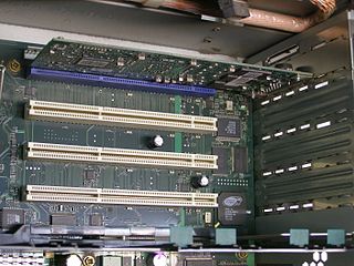
Peripheral Component Interconnect (PCI) is a local computer bus for attaching hardware devices in a computer and is part of the PCI Local Bus standard. The PCI bus supports the functions found on a processor bus but in a standardized format that is independent of any given processor's native bus. Devices connected to the PCI bus appear to a bus master to be connected directly to its own bus and are assigned addresses in the processor's address space. It is a parallel bus, synchronous to a single bus clock. Attached devices can take either the form of an integrated circuit fitted onto the motherboard or an expansion card that fits into a slot. The PCI Local Bus was first implemented in IBM PC compatibles, where it displaced the combination of several slow Industry Standard Architecture (ISA) slots and one fast VESA Local Bus (VLB) slot as the bus configuration. It has subsequently been adopted for other computer types. Typical PCI cards used in PCs include: network cards, sound cards, modems, extra ports such as Universal Serial Bus (USB) or serial, TV tuner cards and hard disk drive host adapters. PCI video cards replaced ISA and VLB cards until rising bandwidth needs outgrew the abilities of PCI. The preferred interface for video cards then became Accelerated Graphics Port (AGP), a superset of PCI, before giving way to PCI Express.

<span class="mw-page-title-main">SCSI</span> Set of computer and peripheral connection standards

Small Computer System Interface is a set of standards for physically connecting and transferring data between computers and peripheral devices, best known for its use with storage devices such as hard disk drives. SCSI was introduced in the 1980s and has seen widespread use on servers and high-end workstations, with new SCSI standards being published as recently as SAS-4 in 2017.

<span class="mw-page-title-main">Ethernet over twisted pair</span> Ethernet physical layers using twisted-pair cables

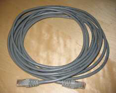
Ethernet over twisted-pair technologies use twisted-pair cables for the physical layer of an Ethernet computer network. They are a subset of all Ethernet physical layers.

<span class="mw-page-title-main">Digital Visual Interface</span> Standard for transmitting digital video to a display

Digital Visual Interface (DVI) is a video display interface developed by the Digital Display Working Group (DDWG). The digital interface is used to connect a video source, such as a video display controller, to a display device, such as a computer monitor. It was developed with the intention of creating an industry standard for the transfer of uncompressed digital video content.

<span class="mw-page-title-main">ST506/ST412</span>

The ST-506 and ST-412 were early hard disk drive products introduced by Seagate in 1980 and 1981 respectively, that later became construed as hard disk drive interfaces: the ST-506 disk interface and the ST-412 disk interface. Compared to the ST-506 precursor, the ST-412 implemented a refinement to the seek speed, and increased the drive capacity from 5 MB to 10 MB, but was otherwise highly similar.

<span class="mw-page-title-main">Low-voltage differential signaling</span> Technical standard

Low-voltage differential signaling (LVDS), also known as TIA/EIA-644, is a technical standard that specifies electrical characteristics of a differential, serial signaling standard. LVDS operates at low power and can run at very high speeds using inexpensive twisted-pair copper cables. LVDS is a physical layer specification only; many data communication standards and applications use it and add a data link layer as defined in the OSI model on top of it.

<span class="mw-page-title-main">SATA</span> Computer bus interface for storage devices

SATA is a computer bus interface that connects host bus adapters to mass storage devices such as hard disk drives, optical drives, and solid-state drives. Serial ATA succeeded the earlier Parallel ATA (PATA) standard to become the predominant interface for storage devices.

<span class="mw-page-title-main">IBM PS/2</span> Second generation of personal computers by IBM

The Personal System/2 or PS/2 is IBM's second generation of personal computers. Released in 1987, it officially replaced the IBM PC, XT, AT, and PC Convertible in IBM's lineup. Many of the PS/2's innovations, such as the 16550 UART, 1440 KB 3.5-inch floppy disk format, 72-pin SIMMs, the PS/2 port, and the VGA video standard, went on to become standards in the broader PC market.

<span class="mw-page-title-main">Host adapter</span> Computer hardware device

In computer hardware, a host controller, host adapter, or host bus adapter (HBA), connects a computer system bus, which acts as the host system, to other network and storage devices. The terms are primarily used to refer to devices for connecting SCSI, SAS, NVMe, Fibre Channel and SATA devices. Devices for connecting to FireWire, USB and other devices may also be called host controllers or host adapters.

Serial Peripheral Interface (SPI) is a de facto standard for synchronous serial communication, used primarily in embedded systems for short-distance wired communication between integrated circuits.

<span class="mw-page-title-main">Electrical termination</span> Transmission line impedance matching

In electronics, electrical termination is the practice of ending a transmission line with a device that matches the characteristic impedance of the line. Termination prevents signals from reflecting off the end of the transmission line. Reflections at the ends of unterminated transmission lines cause distortion, which can produce ambiguous digital signal levels and misoperation of digital systems. Reflections in analog signal systems cause such effects as video ghosting, or power loss in radio transmitter transmission lines.

<span class="mw-page-title-main">PCI-X</span> Computer bus and expansion card standard

PCI-X, short for Peripheral Component Interconnect eXtended, is a computer bus and expansion card standard that enhances the 32-bit PCI local bus for higher bandwidth demanded mostly by servers and workstations. It uses a modified protocol to support higher clock speeds, but is otherwise similar in electrical implementation. PCI-X 2.0 added speeds up to 533 MHz, with a reduction in electrical signal levels.

<span class="mw-page-title-main">Serial Attached SCSI</span> Point-to-point serial protocol for enterprise storage

In computing, Serial Attached SCSI (SAS) is a point-to-point serial protocol that moves data to and from computer-storage devices such as hard disk drives and tape drives. SAS replaces the older Parallel SCSI bus technology that first appeared in the mid-1980s. SAS, like its predecessor, uses the standard SCSI command set. SAS offers optional compatibility with Serial ATA (SATA), versions 2 and later. This allows the connection of SATA drives to most SAS backplanes or controllers. The reverse, connecting SAS drives to SATA backplanes, is not possible.

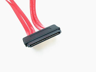
A SCSI connector is used to connect computer parts that use a system called SCSI to communicate with each other. Generally, two connectors, designated male and female, plug together to form a connection which allows two components, such as a computer and a disk drive, to communicate with each other. SCSI connectors can be electrical connectors or optical connectors. There have been a large variety of SCSI connectors in use at one time or another in the computer industry. Twenty-five years of evolution and three major revisions of the standards resulted in requirements for Parallel SCSI connectors that could handle an 8, 16 or 32 bit wide bus running at 5, 10 or 20 megatransfer/s, with conventional or differential signaling. Serial SCSI added another three transport types, each with one or more connector types. Manufacturers have frequently chosen connectors based on factors of size, cost, or convenience at the expense of compatibility.

<span class="mw-page-title-main">SCSI high byte termination</span>

In SCSI computer systems, there is a special case with mixed 8-bit and 16-bit devices where high-byte termination may be required.

<span class="mw-page-title-main">DEC 3000 AXP</span> Series of computer workstations and servers

DEC 3000 AXP was the name given to a series of computer workstations and servers, produced from 1992 to around 1995 by Digital Equipment Corporation. The DEC 3000 AXP series formed part of the first generation of computer systems based on the 64-bit Alpha AXP architecture. Supported operating systems for the DEC 3000 AXP series were DEC OSF/1 AXP and OpenVMS AXP.

Camera Link is a serial communication protocol standard designed for camera interface applications based on the National Semiconductor interface Channel-link. It was designed for the purpose of standardizing scientific and industrial video products including cameras, cables and frame grabbers. The standard is maintained and administered by the Automated Imaging Association or AIA, the global machine vision industry's trade group.

The DEC 7000 AXP and DEC 10000 AXP are a series of high-end multiprocessor server computers developed and manufactured by Digital Equipment Corporation, introduced on 10 November 1992. These systems formed part of the first generation of systems based on the 64-bit Alpha AXP architecture and at the time of introduction, ran Digital's OpenVMS AXP operating system, with DEC OSF/1 AXP available in March 1993. They were designed in parallel with the VAX 7000 and VAX 10000 minicomputers, and are identical except for the processor module(s) and supported bus interfaces. A field upgrade from a VAX 7000/10000 to a DEC 7000/10000 AXP was possible by means of swapping the processor boards.

Hard disk drives are accessed over one of a number of bus types, including parallel ATA, Serial ATA (SATA), SCSI, Serial Attached SCSI (SAS), and Fibre Channel. Bridge circuitry is sometimes used to connect hard disk drives to buses with which they cannot communicate natively, such as IEEE 1394, USB, SCSI, NVMe and Thunderbolt.

References

  1. "T10 Withdrawn Standards and Technical Reports" . Retrieved March 18, 2010.
  2. 1 2 3 4 5 6 7 8 9 "Random Problems Encountered When Mixing SE and LVD SCSI Standards" . Retrieved May 7, 2008.
  3. T10/01-224r0 Ultra640 SCSI Measured Data from Cables & Backplanes.
  4. Scott Mueller: Upgrading and Repairing Servers.
  5. 1 2 3 Scott Mueller; Mark Edward Soper; Barrie Sosinsky (24 April 2006). Upgrading and Repairing Servers. Pearson Education. ISBN   978-0-13-279698-9.
  6. "SCSI Device Unscrewed" . Retrieved 2024-02-22.
  7. "SCSI Adapters and SCSI Controllers Information" . Retrieved 2024-02-22.
  8. Norris, Jim (March 2002). "The Last Word on SCSI". Maximum PC : 50.
  9. M3096GX/M3093GX/M3093DG Image scanner OEM Manual
  10. "Adaptec AHA-2940U2W User's Reference" (PDF). December 1997. Retrieved 2017-05-20.
  11. SCSI-3 Annex B 1996 – SCAM