This article includes a list of general references, but it lacks sufficient corresponding inline citations .(April 2009) |

VMEbus (Versa Module Eurocard [1] bus) is a computer bus standard physically based on Eurocard sizes.
This article includes a list of general references, but it lacks sufficient corresponding inline citations .(April 2009) |
VMEbus (Versa Module Eurocard [1] bus) is a computer bus standard physically based on Eurocard sizes.
In 1979, during development of the Motorola 68000 CPU, one of their engineers, Jack Kister, decided to set about creating a standardized bus system for 68000-based systems. [2] The Motorola team brainstormed for days to select the name VERSAbus. VERSAbus cards were large, 370 by 230 mm (14+1⁄2 by 9+1⁄4 in), and used edge connectors. [3] Only a few products adopted it, including the IBM System 9000 instrument controller and the Automatix robot and machine vision systems.

Kister was later joined by John Black, who refined the specifications and created the VERSAmodule product concept. A young engineer working for Black, Julie Keahey designed the first VERSAmodule card, the VERSAbus Adaptor Module, used to run existing cards on the new VERSAbus. Sven Rau and Max Loesel of Motorola-Europe added a mechanical specification to the system, basing it on the Eurocard standard that was then late in the standardization process. The result was first known as VERSAbus-E but was later renamed to VMEbus, for VERSAmodule Eurocard bus (although some refer to it as Versa Module Europa). [3]
At this point, a number of other companies involved in the 68000's ecosystem agreed to use the standard, including Signetics, Philips, Thomson, and Mostek. Soon it was officially standardized by the IEC as the IEC 821 VMEbus and by ANSI and IEEE as ANSI/IEEE 1014-1987.
The original standard was a 16-bit bus, designed to fit within the existing Eurocard DIN connectors. However, there have been several updates to the system to allow wider bus widths. The current VME64 includes a full 64-bit bus in 6U-sized cards and 32-bit in 3U cards. The VME64 protocol has a typical performance of 40 MB/s. [3] Other associated standards have added hot-swapping (plug-and-play) in VME64x, smaller 'IP' cards that plug into a single VMEbus card, and various interconnect standards for linking VME systems together.
In the late 1990s, synchronous protocols proved to be favourable. The research project was called VME320. The VITA Standards Organization called for a new standard for unmodified VME32/64 backplanes. [3] The new 2eSST protocol was approved in ANSI/VITA 1.5 in 1999.
Over the years, many extensions have been added to the VME interface, providing 'sideband' channels of communication in parallel to VME itself. Some examples are IP Module, RACEway Interlink, SCSA, Gigabit Ethernet on VME64x Backplanes, PCI Express, RapidIO, StarFabric and InfiniBand.
VMEbus was also used to develop closely related standards, VXIbus and VPX. The VMEbus had a strong influence on many later computer buses such as STEbus.
The architectural concepts of the VMEbus are based on VERSAbus, [3] developed in the late 1970s by Motorola. This was later renamed "VME", short for Versa Module European, by Lyman (Lym) Hevle, then a VP with the Motorola Microsystems Operation. (He was later the founder of the VME Marketing Group, itself subsequently renamed to VME International Trade Association, or VITA).
John Black of Motorola, Craig MacKenna of Mostek and Cecil Kaplinsky of Signetics developed the first draft of the VMEbus specification. In October 1981, at the System '81 trade show in Munich, West Germany, Motorola, Mostek, Signetics/Philips, and Thomson CSF announced their joint support of the VMEbus. They also placed Revision A of the specification in the public domain.
In 1985, Aitech developed, under contract for US Army TACOM, the first conduction-cooled 6U VMEbus board. Although electrically providing a compliant VMEbus protocol interface, mechanically, this board was not interchangeable for use in air-cooled lab VMEbus development chassis.
In late 1987, a technical committee was formed under VITA under the direction of IEEE to create the first military, conduction-cooled 6U × 160 mm, fully electrically and mechanically compatible, VMEbus board co-chaired by Dale Young (DY4 Systems) and Doug Patterson (Plessey Microsystems, then Radstone Technology). ANSI/IEEE-1101.2-1992 was later ratified and released in 1992 and remains in place as the conduction-cooled, international standard for all 6U VMEbus products.
In 1989, John Peters of Performance Technologies Inc. developed the initial concept of VME64: multiplexing address and data lines (A64/D64) on the VMEbus. The concept was demonstrated the same year and placed in the VITA Technical Committee in 1990 as a performance enhancement to the VMEbus specification.
In 1993, new activities began on the base-VME architecture, involving the implementation of high-speed serial and parallel sub-buses for use as I/O interconnections and data mover subsystems. These architectures can be used as message switches, routers and small multiprocessor parallel architectures.
VITA's application for recognition as an accredited standards developer organization of ANSI was granted in June 1993. Numerous other documents ( including mezzanine, P2 and serial bus standards) have been placed with VITA as the Public Domain Administrator of these technologies.
| Topology | Year | Bus cycle | Maximum speed (MB/s) |
|---|---|---|---|
| VMEbus32 Parallel Bus Rev. A | 1981 | BLT | 40 |
| VMEbus IEEE-1014 | 1987 | BLT | 40 |
| VME64 | 1994 | MBLT | 80 |
| VME64x | 1997 | 2eVME | 160 |
| VME320 | 1997 | 2eSST | 320 |
In many ways the VMEbus is equivalent or analogous to the pins of the 68000 run out onto a backplane.
However, one of the key features of the 68000 is a flat 32-bit memory model, free of memory segmentation and other "anti-features". The result is that, while VME is very 68000-like, the 68000 is generic enough to make this not an issue in most cases.
Like the 68000, VME uses separate 32-bit data and address buses. The 68000 address bus is actually 24-bit and the data bus 16-bit (although it is 32/32 internally) but the designers were already looking towards a full 32-bit implementation.
In order to allow both bus widths, VME uses two different Eurocard connectors, P1 and P2. P1 contains three rows of 32 pins each, implementing the first 24 address bits, 16 data bits and all of the control signals. P2 contains one more row, which includes the remaining 8 address bits and 16 data bits.
A block transfer protocol allows several bus transfers to occur with a single address cycle. In block transfer mode, the first transfer includes an address cycle and subsequent transfers require only data cycles. The slave is responsible for ensuring that these transfers use successive addresses.
Bus masters can release the bus in two ways. With Release When Done (RWD), the master releases the bus when it completes a transfer and must re-arbitrate for the bus before every subsequent transfer. With Release On Request (ROR), the master retains the bus by continuing to assert BBSY* between transfers. ROR allows the master to retain control over the bus until a Bus Clear (BCLR*) is asserted by another master that wishes to arbitrate for the bus. Thus a master that generates bursts of traffic can optimize its performance by arbitrating for the bus on only the first transfer of each burst. This decrease in transfer latency comes at the cost of somewhat higher transfer latency for other masters.
Address modifiers are used to divide the VME bus address space into several distinct sub-spaces. The address modifier is a 6 bit wide set of signals on the backplane. Address modifiers specify the number of significant address bits, the privilege mode (to allow processors to distinguish between bus accesses by user-level or system-level software), and whether or not the transfer is a block transfer. Below is an incomplete table of address modifiers:
| Hex Code | Function | Explanation |
|---|---|---|
| 3f | Standard Supervisory block transfer | Block transfer A24, privileged |
| 3e | Standard Supervisory Program access | A24 instruction access, privileged |
| 3d | Standard Supervisor Data Access | A24 data access, privileged |
| 3b | Standard Non-privileged block transfer | A24 block transfer for normal programs |
| 3a | Standard Non-privileged Program access | A24 instruction access, non-privileged |
| 39 | Standard non-privileged Data Access | A24 data access, non-privileged |
| 2d | Short supervisory Access | A16 privileged access. |
| 29 | Short non-privileged Access | A16 non-privileged access. |
| 0f | Extended supervisory Block transfer | A32 privileged block transfer. |
| 0e | Extended supervisory Program access | A32 privileged instruction access. |
| 0d | Extended supervisory Data Access. | A32 privileged data access. |
| 0b | Extended Non-privileged Block transfer | A32 non-privileged block transfer. |
| 0a | Extended Non-privileged Program access | A32 non-privileged instruction access. |
| 09 | Extended non-privileged data access. | A32 non-privileged data access. |
| Note | An as in A16, A24, A32 refers to the width of the address |
On the VME bus, all transfers are DMA and every card is a master or slave. In most bus standards, there is a considerable amount of complexity added in order to support various transfer types and master/slave selection. For instance, with the ISA bus, both of these features had to be added alongside the existing "channels" model, whereby all communications was handled by the host CPU. This makes VME considerably simpler at a conceptual level while being more powerful, though it requires more complex controllers on each card.
When developing and/or troubleshooting the VME bus, examination of hardware signals can be very important. Logic analyzers and bus analyzers are tools that collect, analyze, decode, store signals so people can view the high-speed waveforms at their leisure.
VITA offers a comprehensive FAQ to assist with the front end design and development of VME systems.
Computers using VMEbus include:
Seen looking into backplane socket. [5] [6]
P1
| Pin | a | b | c |
|---|---|---|---|
| 1 | D00 | BBSY* | D08 |
| 2 | D01 | BCLR* | D09 |
| 3 | D02 | ACFAIL* | D10 |
| 4 | D03 | BG0IN* | D11 |
| 5 | D04 | BG0OUT* | D12 |
| 6 | D05 | BG1IN* | D13 |
| 7 | D06 | BG1OUT* | D14 |
| 8 | D07 | BG2IN* | D15 |
| 9 | GND | BG2OUT* | GND |
| 10 | SYSCLK | BG3IN* | SYSFAIL* |
| 11 | GND | BG3OUT* | BERR* |
| 12 | DS1* | BR0* | SYSRESET* |
| 13 | DS0* | BR1* | LWORD* |
| 14 | WRITE* | BR2* | AM5 |
| 15 | GND | BR3* | A23 |
| 16 | DTACK* | AM0 | A22 |
| 17 | GND | AM1 | A21 |
| 18 | AS* | AM2 | A20 |
| 19 | GND | AM3 | A19 |
| 20 | IACK* | GND | A18 |
| 21 | IACKIN* | SERCLK | A17 |
| 22 | IACKOUT* | SERDAT* | A16 |
| 23 | AM4 | GND | A15 |
| 24 | A07 | IRQ7* | A14 |
| 25 | A06 | IRQ6* | A13 |
| 26 | A05 | IRQ5* | A12 |
| 27 | A04 | IRQ4* | A11 |
| 28 | A03 | IRQ3* | A10 |
| 29 | A02 | IRQ2* | A09 |
| 30 | A01 | IRQ1* | A08 |
| 31 | −12V | +5VSTDBY | +12V |
| 32 | +5V | +5V | +5V |
P2
| Pin | a | b | c |
|---|---|---|---|
| 1 | User Defined | +5V | User Defined |
| 2 | User Defined | GND | User Defined |
| 3 | User Defined | RESERVED | User Defined |
| 4 | User Defined | A24 | User Defined |
| 5 | User Defined | A25 | User Defined |
| 6 | User Defined | A26 | User Defined |
| 7 | User Defined | A27 | User Defined |
| 8 | User Defined | A28 | User Defined |
| 9 | User Defined | A29 | User Defined |
| 10 | User Defined | A30 | User Defined |
| 11 | User Defined | A31 | User Defined |
| 12 | User Defined | GND | User Defined |
| 13 | User Defined | +5V | User Defined |
| 14 | User Defined | D16 | User Defined |
| 15 | User Defined | D17 | User Defined |
| 16 | User Defined | D18 | User Defined |
| 17 | User Defined | D19 | User Defined |
| 18 | User Defined | D20 | User Defined |
| 19 | User Defined | D21 | User Defined |
| 20 | User Defined | D22 | User Defined |
| 21 | User Defined | D23 | User Defined |
| 22 | User Defined | GND | User Defined |
| 23 | User Defined | D24 | User Defined |
| 24 | User Defined | D25 | User Defined |
| 25 | User Defined | D26 | User Defined |
| 26 | User Defined | D27 | User Defined |
| 27 | User Defined | D28 | User Defined |
| 28 | User Defined | D29 | User Defined |
| 29 | User Defined | D30 | User Defined |
| 30 | User Defined | D31 | User Defined |
| 31 | User Defined | GND | User Defined |
| 32 | User Defined | +5V | User Defined |
P2 rows a and c can be used by a secondary bus, for example the STEbus.

Eurocard is an IEEE standard format for printed circuit board (PCB) cards that can be plugged together into a standard chassis which, in turn, can be mounted in a 19-inch rack. The chassis consists of a series of slotted card guides on the top and bottom, into which the cards are slid so they stand on end, like books on a shelf. At the spine of each card is one or more connectors which plug into mating connectors on a backplane that closes the rear of the chassis.
Futurebus is a computer bus standard designed to replace all local bus connections in a computer, including the CPU, plug-in cards, and even some LAN links between machines. The project started in 1979 and was completed in 1987, but then went through a redesign until 1994. It has seen little real-world use, although custom implementations are still designed.
A PCI Mezzanine Card or PMC is a printed circuit board assembly manufactured to the IEEE P1386.1 standard. This standard combines the electrical characteristics of the PCI bus with the mechanical dimensions of the Common Mezzanine Card or CMC format.

Electronic test equipment is used to create signals and capture responses from electronic devices under test (DUTs). In this way, the proper operation of the DUT can be proven or faults in the device can be traced. Use of electronic test equipment is essential to any serious work on electronics systems.

CompactPCI is a computer bus interconnect for industrial computers, combining a Eurocard-type connector and PCI signaling and protocols. Boards are standardized to 3U or 6U sizes, and are typically interconnected via a passive backplane. The connector pin assignments are standardized by the PICMG US and PICMG Europe organizations. The connectors and the electrical rules allow for eight boards in a PCI segment. Multiple bus segments are allowed with bridges.
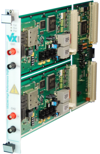
VME eXtensions for instrumentation bus refers to standards for automated test based upon VMEbus. VXI defines additional bus lines for timing and triggering as well as mechanical requirements and standard protocols for configuration, message-based communication, multi-chassis extension, and other features. In 2004, the 2eVME extension was added to the VXI bus specification, giving it a maximum data rate of 160 MB/s.

Multibus is a computer bus standard used in industrial systems. It was developed by Intel Corporation and was adopted as the IEEE 796 bus.
The STEbus is a non-proprietary, processor-independent, computer bus with 8 data lines and 20 address lines. It was popular for industrial control systems in the late 1980s and early 1990s before the ubiquitous IBM PC dominated this market. STE stands for STandard Eurocard.

Computer-Aided Measurement And Control (CAMAC) is a standard bus and modular-crate electronics standard for data acquisition and control used in particle detectors for nuclear and particle physics and in industry. The bus allows data exchange between plug-in modules and a crate controller, which then interfaces to a PC or to a VME-CAMAC interface.

A system on a module (SoM) is a board-level circuit that integrates a system function in a single module. It may integrate digital and analog functions on a single board. A typical application is in the area of embedded systems. Unlike a single-board computer, a SoM serves a special function like a system on a chip (SoC). The devices integrated in the SoM typically requires a high level of interconnection for reasons such as speed, timing, bus width, etc. There are benefits in building a SoM, as for SoC; one notable result is to reduce the cost of the base board or the main PCB. Two other major advantages of SoMs are design-reuse and that they can be integrated into many embedded computer applications.

VPX, also known as VITA 46, is a set of standards for connecting components of a computer, commonly used by defense contractors. Some are ANSI standards such as ANSI/VITA 46.0–2019. VPX provides VMEbus-based systems with support for switched fabrics over a new high speed connector. Defined by the VMEbus International Trade Association (VITA) working group starting in 2003, it was first demonstrated in 2004, and became an ANSI standard in 2007.
DIN 41612 was a DIN standard for electrical connectors that are widely used in rack based electrical systems. Standardisation of the connectors is a pre-requisite for open systems, where users expect components from different suppliers to operate together. The most widely known use of DIN 41612 connectors is in the VMEbus and NuBus systems. The standard has withdrawn in favor of international standards IEC 60603-2 and EN 60603-2.
M-Modules are a mezzanine standard mainly used in industrial computers. Being mezzanines, they are always plugged on a carrier printed circuit board (PCB) that supports this format. The modules communicate with their carrier over a dedicated bus, and can have all kinds of special functions.
CompactPCI PlusIO is an extension to the PICMG 2.0 CompactPCI industrial standard for modular computer systems. CompactPCI PlusIO was officially adopted by the PCI Industrial Computer Manufacturers Group PICMG as PICMG 2.30 CompactPCI PlusIO in November 2009. Being 100% compatible with CompactPCI, PICMG 2.30 defines a migration path to the future CompactPCI Serial standard. It defines a fixed rear I/O pin assignment that focuses on modern, fast serial point-to-point connections. The new technology succeeding parallel CompactPCI comprises both CompactPCI Serial and CompactPCI PlusIO.
CompactPCI Serial is an industrial standard for modular computer systems. It is based on the established PICMG 2.0 CompactPCI standard, which uses the parallel PCI bus for communication among a system's card components. In contrast to this, CompactPCI Serial uses only serial point-to-point connections. CompactPCI Serial was officially adopted by the PCI Industrial Computer Manufacturers Group PICMG as PICMG CPCI-S.0 CompactPCI Serial in March 2011. Its mechanical concept is based on the proven standards of IEEE 1101-1-1998 and IEEE 1101-10-1996. CompactPCI Serial includes different connectors that permit very high data rates. The new technology standard succeeding parallel CompactPCI comprises another specification called PICMG 2.30 CompactPCI PlusIO. This is why CompactPCI Serial and CompactPCI PlusIO as a whole were also called CompactPCI Plus. PICMG's first working title of CompactPCI Serial was CPLUS.0. CompactPCI Serial backplanes and chassis are developed by Schroff, Elmа, and Pixus Technologies companies, as for the CompactPCI Serial board level electronics – they are developed by MEN Mikro Elektronik, Fastwel, EKF, Emerson Embedded Computing, ADLINK, and Kontron.
GreenSpring Computers was a computer manufacturer founded in 1984 by Leonard and Henry Lehmann in Redwood City, California.
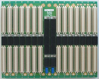
Elma Electronic is a publicly traded Swiss electronics company founded in 1960 and based in Wetzikon, Switzerland. The company has 5 product divisions: Systems Platforms, Backplanes, Enclosures & Components, Rotary Switches, and Cabinet Enclosures. The largest segment is systems packaging serving the military, aerospace, homeland security, medical and industrial markets. The Elma Bustronic division develops backplanes, including VME320, which was the world's fastest VME backplane in 1997. Elma Bustronic also develops backplanes in OpenVPX, VMEbus, VME64X, CompactPCI, MicroTCA, and custom bus structures. Elma is an executive member of the PCI Industrial Computer Manufacturers Group (PICMG), VME International Trade Association, and member of the OpenVPX Industry Working Standards Group.
The Europe Card Bus is a computer bus developed in 1977 by the company Kontron, mainly for the 8-bit Zilog Z80, Intel 8080 and Intel 8085 microprocessor families.
VMEBus Switched Serial, commonly known as VXS, is an ANSI standard that improves the performance of standard parallel VMEbus by enhancing it to support newer switched serial fabrics. The base specification defines all common elements of the standard, while "dot"-specifications define extensions which use specific serial fabrics or additional functionality. VXS is backward compatible with VMEBus. It is defined by the VME International Trade Association (VITA) working group.

Modular crate electronics are a general type of electronics and support infrastructure commonly used for trigger electronics and data acquisition in particle detectors. These types of electronics are common in such detectors because all the electronic pathways are made by discrete physical cables connecting together logic blocks on the fronts of modules. This allows circuits to be designed, built, tested, and deployed very quickly as an experiment is being put together. Then the modules can all be removed and used again when the experiment is done.
A team of engineers at Motorola Microsystems led by Jack Kister, designed a 68000 development system called the EXORmacs. The backplane of the EXORmacs was called VERSAbus. While coordinating the efforts of his team, Jack wrote a 41-page bus description of VERSAbus which was published in November of 1979. The first EXORmacs was shipped in January 1980.
| General | |
|---|---|
| Standards |
|
| Storage |
|
| Peripheral | |
| Audio | |
| Portable | |
| Embedded | |
Interfaces are listed by their speed in the (roughly) ascending order, so the interface at the end of each section should be the fastest. | |