The OR gate is a digital logic gate that implements logical disjunction. The OR gate outputs "true" if any of its inputs is "true"; otherwise it outputs "false". The input and output states are normally represented by different voltage levels.
Any OR gate can be constructed with two or more inputs. It outputs a 1 if any of these inputs are 1, or outputs a 0 only if all inputs are 0. The inputs and outputs are binary digits ("bits") which have two possible logical states. In addition to 1 and 0, these states may be called true and false, high and low, active and inactive, or other such pairs of symbols.
Thus it performs a logical disjunction (∨) from mathematical logic. The gate can be represented with the plus sign (+) because it can be used for logical addition.[1] Equivalently, an OR gate finds the maximum between two binary digits, just as the AND gate finds the minimum.[2]
Together with the AND gate and the NOT gate, the OR gate is one of three basic logic gates from which any Boolean circuit may be constructed. All other logic gates may be made from these three gates; any function in binary mathematics may be implemented with them.[3]
It is sometimes called the inclusive OR gate to distinguish it from XOR, the exclusive OR gate.[4] The behavior of OR is the same as XOR except in the case of a 1 for both inputs. In situations where this never arises (for example, in a full-adder) the two types of gates are interchangeable. This substitution is convenient when a circuit is being implemented using simple integrated circuit chips which contain only one gate type per chip.
Symbols
There are two logic gate symbols currently representing the OR gate: the American (ANSI or 'military') symbol and the IEC ('European' or 'rectangular') symbol. The DIN symbol is deprecated.[5][6]
The "≥1" on the IEC symbol indicates that the output is activated by at least one active input.[7]
This schematic diagram shows the arrangement of four OR gates within a standard 4071 CMOS integrated circuit.
OR gates are basic logic gates, and are available in TTL and CMOSICslogic families. The standard 4000 series CMOS IC is the 4071, which includes four independent two-input OR gates. The TTL device is the 7432. There are many offshoots of the original 7432 OR gate, all having the same pinout but different internal architecture, allowing them to operate in different voltage ranges and/or at higher speeds. In addition to the standard 2-input OR gate, 3- and 4-input OR gates are also available. In the CMOS series, these are:
4075: triple 3-input OR gate
4072: dual 4-input OR gate
Variations include:
74LS32: quad 2-input OR gate (low power Schottky version)
74HC32: quad 2-input OR gate (high speed CMOS version) - has lower current consumption/wider voltage range
74AC32: quad 2-input OR gate (advanced CMOS version) - similar to 74HC32, but with significantly faster switching speeds and stronger drive
OR gates with multiple inputs are designated with the same symbol, with more lines leading in.[8] While direct implementations with more than three inputs are possible in logic families like CMOS, these are inefficient. More efficient implementations use a cascade of NOR and NAND gates, as shown in the picture below.
12-input OR gate realized via a cascade of NOR and NAND gates.
If no specific OR gates are available, one can be made from NAND or NOR gates in the configuration shown in the image below. Any logic gate can be made from a combination of NAND or NOR gates.
Desired gate
NAND construction
NOR construction
Wired-OR
Wired OR gate using open-collector NOR gates
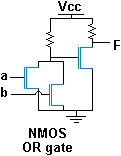
With active lowopen collector logic outputs, as used for control signals in many circuits, an OR function can be produced by wiring together several outputs. This arrangement is called a wired OR. This implementation of an OR function typically is also found in integrated circuits of N or P-type only transistor processes.
↑ Harris, David Harris, Sarah (2007). Digital design and computer architecture (1sted.). San Francisco, Calif.: Morgan Kaufmann. p.21. ISBN9780123704979.{{cite book}}: CS1 maint: multiple names: authors list (link)
↑ Brumbach, Michael E. (January 2010). Industrial electricity (8thed.). Clifton Park, N.Y.: Delmar. p.546. ISBN9781435483743.
This page is based on this Wikipedia article Text is available under the CC BY-SA 4.0 license; additional terms may apply. Images, videos and audio are available under their respective licenses.