
The ionosphere is the ionized part of Earth's upper atmosphere, from about 48 km (30 mi) to 965 km (600 mi) altitude, a region that includes the thermosphere and parts of the mesosphere and exosphere. The ionosphere is ionized by solar radiation. It plays an important role in atmospheric electricity and forms the inner edge of the magnetosphere. It has practical importance because, among other functions, it influences radio propagation to distant places on the Earth.

Microwave is a form of electromagnetic radiation with wavelengths ranging from about one meter to one millimeter corresponding to frequencies between 300 MHz and 300 GHz respectively. Different sources define different frequency ranges as microwaves; the above broad definition includes both UHF and EHF bands. A more common definition in radio-frequency engineering is the range between 1 and 100 GHz. In all cases, microwaves include the entire SHF band at minimum. Frequencies in the microwave range are often referred to by their IEEE radar band designations: S, C, X, Ku, K, or Ka band, or by similar NATO or EU designations.

Line-of-sight propagation is a characteristic of electromagnetic radiation or acoustic wave propagation which means waves travel in a direct path from the source to the receiver. Electromagnetic transmission includes light emissions traveling in a straight line. The rays or waves may be diffracted, refracted, reflected, or absorbed by the atmosphere and obstructions with material and generally cannot travel over the horizon or behind obstacles.

Radio waves are a type of electromagnetic radiation with wavelengths in the electromagnetic spectrum longer than infrared light. Radio waves have frequencies as high as 300 gigahertz (GHz) to as low as 30 hertz (Hz). At 300 GHz, the corresponding wavelength is 1 mm ; at 30 Hz the corresponding wavelength is 10,000 km. Like all electromagnetic waves, radio waves in a vacuum travel at the speed of light, and in the Earth's atmosphere at a close, but slightly lower speed. Radio waves are generated by charged particles undergoing acceleration, such as time-varying electric currents. Naturally occurring radio waves are emitted by lightning and astronomical objects, and are part of the blackbody radiation emitted by all warm objects.

Medium wave (MW) is the part of the medium frequency (MF) radio band used mainly for AM radio broadcasting. The spectrum provides about 120 channels with limited sound quality. During daytime, only local stations can be received. Propagation in the night allows strong signals within a range of about 2,000 km. This can cause massive interference because on most channels, about 20 to 50 transmitters operate simultaneously worldwide. In addition to that, amplitude modulation (AM) is prone to interference by all sorts of electronic devices, especially power supplies and computers. Strong transmitters cover larger areas than on the FM broadcast band but require more energy. Digital modes are possible but have not reached the momentum yet.
Very low frequency or VLF is the ITU designation for radio frequencies (RF) in the range of 3–30 kHz, corresponding to wavelengths from 100 to 10 km, respectively. The band is also known as the myriameter band or myriameter wave as the wavelengths range from one to ten myriameters. Due to its limited bandwidth, audio (voice) transmission is highly impractical in this band, and therefore only low data rate coded signals are used. The VLF band is used for a few radio navigation services, government time radio stations and for secure military communication. Since VLF waves can penetrate at least 40 meters (131 ft) into saltwater, they are used for military communication with submarines.
Low frequency (LF) is the ITU designation for radio frequencies (RF) in the range of 30–300 kHz. Since its wavelengths range from 10–1 km, respectively, it is also known as the kilometre band or kilometre wave.

Medium frequency (MF) is the ITU designation for radio frequencies (RF) in the range of 300 kilohertz (kHz) to 3 megahertz (MHz). Part of this band is the medium wave (MW) AM broadcast band. The MF band is also known as the hectometer band as the wavelengths range from ten to one hectometer. Frequencies immediately below MF are denoted low frequency (LF), while the first band of higher frequencies is known as high frequency (HF). MF is mostly used for AM radio broadcasting, navigational radio beacons, maritime ship-to-shore communication, and transoceanic air traffic control.
Radio propagation is the behavior of radio waves as they travel, or are propagated, from one point to another, or into various parts of the atmosphere. As a form of electromagnetic radiation, like light waves, radio waves are affected by the phenomena of reflection, refraction, diffraction, absorption, polarization, and scattering. Understanding the effects of varying conditions on radio propagation has many practical applications, from choosing frequencies for international shortwave broadcasters, to designing reliable mobile telephone systems, to radio navigation, to operation of radar systems.
In radio communication, skywave or skip refers to the propagation of radio waves reflected or refracted back toward Earth from the ionosphere, an electrically charged layer of the upper atmosphere. Since it is not limited by the curvature of the Earth, skywave propagation can be used to communicate beyond the horizon, at intercontinental distances. It is mostly used in the shortwave frequency bands.
A guy-wire, guy-line, or guy-rope, also known as simply a guy, is a tensioned cable designed to add stability to a free-standing structure. They are used commonly for ship masts, radio masts, wind turbines, utility poles, and tents. A thin vertical mast supported by guy wires is called a guyed mast. Structures that support antennas are frequently of a lattice construction and are called "towers". One end of the guy is attached to the structure, and the other is anchored to the ground at some distance from the mast or tower base. The tension in the diagonal guy-wire, combined with the compression and buckling strength of the structure, allows the structure to withstand lateral loads such as wind or the weight of cantilevered structures. They are installed radially, usually at equal angles about the structure, in trios and quads. As the tower leans a bit due to the wind force, the increased guy tension is resolved into a compression force in the tower or mast and a lateral force that resists the wind load. For example, antenna masts are often held up by three guy-wires at 120° angles. Structures with predictable lateral loads, such as electrical utility poles, may require only a single guy-wire to offset the lateral pull of the electrical wires, at a spot where the wires change direction.

Grimeton Radio Station in southern Sweden, close to Varberg in Halland, is an early longwave transatlantic wireless telegraphy station built in 1922–1924, that has been preserved as a historical site. From the 1920s through the 1940s it was used to transmit telegram traffic by Morse code to North America and other countries, and during World War II was Sweden's only telecommunication link with the rest of the world. It is the only remaining example of an early pre-electronic radio transmitter technology called an Alexanderson alternator. It was added to the UNESCO World Heritage List in 2004, with the statement: "Grimeton Radio Station, Varberg is an outstanding monument representing the process of development of communication technology in the period following the First World War." The radio station is also an anchor site for the European Route of Industrial Heritage. The transmitter is still in operational condition, and each year on a day called Alexanderson Day is started up and transmits brief Morse code test transmissions, which can be received all over Europe.

The Mainflingen mediumwave transmitter is a mediumwave transmission facility south of the A3 motorway near Mainflingen, Hesse, Germany. Mainflingen was the first mediumwave transmitter for the radio station Deutschlandfunk. It went into service in 1962 with a transmission power of 50 kW, on a frequency of 1538 kHz, at the upper end of the mediumwave band. This frequency has a bad groundwave propagation and therefore a low range at daytime, but an excellent skywave propagation with a long range at night.
Radio masts and towers are typically tall structures designed to support antennas for telecommunications and broadcasting, including television. There are two main types: guyed and self-supporting structures. They are among the tallest human-made structures. Masts are often named after the broadcasting organizations that originally built them or currently use them.
A mast radiator is a radio mast or tower in which the metal structure itself is energized and functions as an antenna. This design, first used widely in the 1930s, is commonly used for transmitting antennas operating at low frequencies, in the LF and MF bands, in particular those used for AM radio broadcasting stations. The conductive steel mast is electrically connected to the transmitter. Its base is usually mounted on a nonconductive support to insulate it from the ground. A mast radiator is a form of monopole antenna.
A broadcast transmitter is an electronic device which radiates radio waves modulated with information content intended to be received by the general public. Examples are a radio broadcasting transmitter which transmits audio (sound) to broadcast radio receivers (radios) owned by the public, or a television transmitter, which transmits moving images (video) to television receivers (televisions). The term often includes the antenna which radiates the radio waves, and the building and facilities associated with the transmitter. A broadcasting station consists of a broadcast transmitter along with the production studio which originates the broadcasts. Broadcast transmitters must be licensed by governments, and are restricted to specific frequencies and power levels. Each transmitter is assigned a unique identifier consisting of a string of letters and numbers called a callsign, which must be used in all broadcasts.
Non-line-of-sight (NLOS) radio propagation occurs outside of the typical line of sight (LOS) between the transmitter and receiver, such as in ground reflections. Near-line-of-sight conditions refer to partial obstruction by a physical object present in the innermost Fresnel zone.
Near vertical incidence skywave, or NVIS, is a skywave radio-wave propagation path that provides usable signals in the distances range — usually 0–650 km (0–400 miles). It is used for military and paramilitary communications, broadcasting, especially in the tropics, and by radio amateurs for nearby contacts circumventing line-of-sight barriers. The radio waves travel near-vertically upwards into the ionosphere, where they are refracted back down and can be received within a circular region up to 650 km from the transmitter. If the frequency is too high, refraction fails to occur and if it is too low, absorption in the ionospheric D layer may reduce the signal strength.
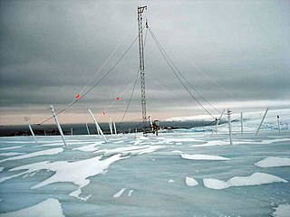
An umbrella antenna is a capacitively top-loaded wire monopole antenna, consisting in most cases of a mast fed at the ground end, to which a number of radial wires are connected at the top, sloping downwards. They are used as transmitting antennas below 1 MHz, in the MF, LF and particularly the VLF bands, at frequencies sufficiently low that it is impractical or infeasible to build a full size quarter-wave monopole antenna. The outer end of each radial wire, sloping down from the top of the antenna, is connected by an insulator to a supporting rope or (usually) insulated cable anchored to the ground; the radial wires can also support the mast as guy wires. The radial wires make the antenna look like the frame of a giant umbrella – without the cloth – hence the name.

In radio communication, a ground dipole, also referred to as an earth dipole antenna, transmission line antenna, and in technical literature as a horizontal electric dipole (HED), is a huge, specialized type of radio antenna that radiates extremely low frequency (ELF) electromagnetic waves. It is the only type of transmitting antenna that can radiate practical amounts of power in the frequency range of 3 Hz to 3 kHz, commonly called ELF waves A ground dipole consists of two ground electrodes buried in the earth, separated by tens to hundreds of kilometers, linked by overhead transmission lines to a power plant transmitter located between them. Alternating current electricity flows in a giant loop between the electrodes through the ground, radiating ELF waves, so the ground is part of the antenna. To be most effective, ground dipoles must be located over certain types of underground rock formations. The idea was proposed by U.S. Dept. of Defense physicist Nicholas Christofilos in 1959.
