Description
These representations are used to describe corresponding changes in crankshaft angle and port-area.
A Kramer graph plots the relation of the open area of various ports with respect to the angle of the crankshaft in a two-stroke engine. So that upon completion of the cycle (one revolution of 360°) there has been no net change in state of the system; i.e. the device returns to the starting position and area which is zero.
They do not show the specific configuration of ports like in a port-map, which enables it to illustrate a more useful visualization of port area distribution,
This could be useful because different types of port configurations could have the same opening time and area.

A piston is a component of reciprocating engines, reciprocating pumps, gas compressors, hydraulic cylinders and pneumatic cylinders, among other similar mechanisms. It is the moving component that is contained by a cylinder and is made gas-tight by piston rings. In an engine, its purpose is to transfer force from expanding gas in the cylinder to the crankshaft via a piston rod and/or connecting rod. In a pump, the function is reversed and force is transferred from the crankshaft to the piston for the purpose of compressing or ejecting the fluid in the cylinder. In some engines, the piston also acts as a valve by covering and uncovering ports in the cylinder.

In engineering, the Miller cycle is a thermodynamic cycle used in a type of internal combustion engine. The Miller cycle was patented by Ralph Miller, an American engineer, US patent 2817322 dated Dec 24, 1957. The engine may be two- or four-stroke and may be run on diesel fuel, gases, or dual fuel.
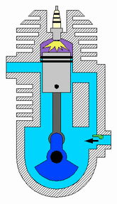
A two-strokeengine is a type of internal combustion engine that completes a power cycle with two strokes of the piston during only one crankshaft revolution. This is in contrast to a four-stroke engine, which requires four strokes of the piston to complete a power cycle during two crankshaft revolutions. In a two-stroke engine, the end of the combustion stroke and the beginning of the compression stroke happen simultaneously, with the intake and exhaust functions occurring at the same time.
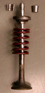
A poppet valve is a valve typically used to control the timing and quantity of gas or vapor flow into an engine.

A four-strokeengine is an internal combustion (IC) engine in which the piston completes four separate strokes while turning the crankshaft. A stroke refers to the full travel of the piston along the cylinder, in either direction. The four separate strokes are termed:
- Intake: Also known as induction or suction. This stroke of the piston begins at top dead center (T.D.C.) and ends at bottom dead center (B.D.C.). In this stroke the intake valve must be in the open position while the piston pulls an air-fuel mixture into the cylinder by producing vacuum pressure into the cylinder through its downward motion. The piston is moving down as air is being sucked in by the downward motion against the piston.
- Compression: This stroke begins at B.D.C, or just at the end of the suction stroke, and ends at T.D.C. In this stroke the piston compresses the air-fuel mixture in preparation for ignition during the power stroke (below). Both the intake and exhaust valves are closed during this stage.
- Combustion: Also known as power or ignition. This is the start of the second revolution of the four stroke cycle. At this point the crankshaft has completed a full 360 degree revolution. While the piston is at T.D.C. the compressed air-fuel mixture is ignited by a spark plug or by heat generated by high compression, forcefully returning the piston to B.D.C. This stroke produces mechanical work from the engine to turn the crankshaft.
- Exhaust: Also known as outlet. During the exhaust stroke, the piston, once again, returns from B.D.C. to T.D.C. while the exhaust valve is open. This action expels the spent air-fuel mixture through the exhaust valve.
The engine configuration describes the fundamental operating principles by which internal combustion engines are categorized.
The Atkinson-cycle engine is a type of internal combustion engine invented by James Atkinson in 1882. The Atkinson cycle is designed to provide efficiency at the expense of power density.

The valve gear of a steam engine is the mechanism that operates the inlet and exhaust valves to admit steam into the cylinder and allow exhaust steam to escape, respectively, at the correct points in the cycle. It can also serve as a reversing gear. It is sometimes referred to as the "motion".

The Junkers Jumo 205 aircraft engine was the most famous of a series of aircraft diesel engines that were the first, and for more than half a century, the only successful aviation diesel powerplants. The Jumo 204 first entered service in 1932. Later engines of this type comprised the experimental Jumo 206 and Jumo 208, with the Jumo 207 produced in some quantity for the Junkers Ju 86P and -R high-altitude reconnaissance aircraft, and the 46-meter wingspan, six-engined Blohm & Voss BV 222 Wiking flying boat. All three of these variants differed in stroke and bore and supercharging arrangements. In all, more than 900 of these engines were produced, in the 1930s and through most of World War II.

The Monosoupape, was a rotary engine design first introduced in 1913 by Gnome Engine Company. It used a clever arrangement of internal transfer ports and a single pushrod-operated exhaust valve to replace the many moving parts found on more conventional rotary engines, and made the Monosoupape engines some of the most reliable of the era. British aircraft designer Thomas Sopwith described the Monosoupape as "one of the greatest single advances in aviation".

In internal combustion engines, variable valve timing (VVT) is the process of altering the timing of a valve lift event, and is often used to improve performance, fuel economy or emissions. It is increasingly being used in combination with variable valve lift systems. There are many ways in which this can be achieved, ranging from mechanical devices to electro-hydraulic and camless systems. Increasingly strict emissions regulations are causing many automotive manufacturers to use VVT systems.
The Junkers Jumo 204 was the second in a series of German aircraft Diesel engines. The Jumo 204 first entered service in 1932. Later engines in the series were designated Jumo 205, Jumo 206, Jumo 207 and Jumo 208, they differed in stroke and bore and supercharging arrangements.

Reed valves are a type of check valve which restrict the flow of fluids to a single direction, opening and closing under changing pressure on each face. Modern versions often consist of flexible metal or composite materials.

Alfa Romeo Twin Spark (TS) technology was used for the first time in the Alfa Romeo Grand Prix car in 1914. In the early 1960s it was used in their race cars to enable it to achieve a higher power output from its engines. And in the early and middle 1980s, Alfa Romeo incorporated this technology into their road cars to enhance their performance and to comply with stricter emission controls.
In a piston engine, the valve timing is the precise timing of the opening and closing of the valves. In an internal combustion engine those are usually poppet valves and in a steam engine they are usually slide valves or piston valves.
In the context of an internal combustion engine, the term stroke has the following related meanings

Scavenging is the process of replacing the exhaust gas in a cylinder of an internal combustion engine with the fresh air/fuel mixture for the next cycle. If scavenging is incomplete, the remaining exhaust gases can cause improper combustion for the next cycle, leading to reduced power output.

A two-stroke diesel engine is a diesel engine that works by combining what is normally four cycles – intake, compression, combustion, and exhaust into only two strokes of the engine. It was invented by Hugo Güldner in 1899.
Internal combustion engines come in a wide variety of types, but have certain family resemblances, and thus share many common types of components.

An internal combustion engine (ICE) is a heat engine in which the combustion of a fuel occurs with an oxidizer in a combustion chamber that is an integral part of the working fluid flow circuit. In an internal combustion engine, the expansion of the high-temperature and high-pressure gases produced by combustion applies direct force to some component of the engine. The force is applied typically to pistons, turbine blades, a rotor, or a nozzle. This force moves the component over a distance, transforming chemical energy into useful work. This replaced the external combustion engine for applications where weight or size of the engine is important.