An electric motor is an electrical machine that converts electrical energy into mechanical energy. Most electric motors operate through the interaction between the motor's magnetic field and electric current in a wire winding to generate force in the form of torque applied on the motor's shaft. An electric generator is mechanically identical to an electric motor, but operates in reverse, converting mechanical energy into electrical energy.

A stepper motor, also known as step motor or stepping motor, is an electrical motor that rotates in a series of small angular steps, instead of continuously. Stepper motors are a type of digital actuator. Like other electromagnetic actuators, they convert electric energy into mechanical position can be commanded to move and hold at one of these steps without any position sensor for feedback, as long as the motor is correctly sized to the application in respect to torque and speed.

A synchronous electric motor is an AC electric motor in which, at steady state, the rotation of the shaft is synchronized with the frequency of the supply current; the rotation period is exactly equal to an integer number of AC cycles. Synchronous motors use electromagnets as the stator of the motor which create a magnetic field that rotates in time with the oscillations of the current. The rotor with permanent magnets or electromagnets turns in step with the stator field at the same rate and as a result, provides the second synchronized rotating magnet field. A synchronous motor is termed doubly fed if it is supplied with independently excited multiphase AC electromagnets on both the rotor and stator.

A brushless DC electric motor (BLDC), also known as an electronically commutated motor, is a synchronous motor using a direct current (DC) electric power supply. It uses an electronic controller to switch DC currents to the motor windings producing magnetic fields that effectively rotate in space and which the permanent magnet rotor follows. The controller adjusts the phase and amplitude of the current pulses that control the speed and torque of the motor. It is an improvement on the mechanical commutator (brushes) used in many conventional electric motors.

A DC motor is an electrical motor that uses direct current (DC) to produce mechanical force. The most common types rely on magnetic forces produced by currents in the coils. Nearly all types of DC motors have some internal mechanism, either electromechanical or electronic, to periodically change the direction of current in part of the motor.

The shaded-pole motor is the original type of AC single-phase motor, dating back to at least as early as 1890. A shaded-pole motor is a small motor with either two or four poles, in which the auxiliary winding is composed of a copper ring or bar surrounding a portion of each pole to produce a weakly rotating magnetic field. When single phase AC supply is applied to the stator winding, due to shading provided to the poles, a rotating magnetic field is generated. This auxiliary single-turn winding is called a shading coil. Currents induced in this coil by the magnetic field create a second electrical phase by delaying the phase of magnetic flux change for that pole enough to provide a 2-phase rotating magnetic field. The direction of rotation is from the unshaded side to the shaded (ring) side of the pole. Since the phase angle between the shaded and unshaded sections is small, shaded-pole motors produce only a small starting torque relative to torque at full speed. Shaded-pole motors of the asymmetrical type shown are only reversible by disassembly and flipping over the stator, though some similar looking motors have small, switch-shortable auxiliary windings of thin wire instead of thick copper bars and can reverse electrically. Another method of electrical reversing involves four coils.

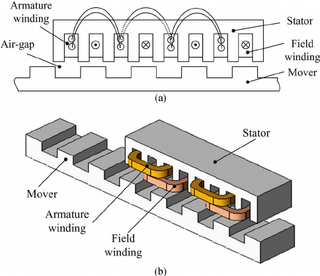
In electrical engineering, the armature is the winding of an electric machine which carries alternating current. The armature windings conduct AC even on DC machines, due to the commutator action or due to electronic commutation, as in brushless DC motors. The armature can be on either the rotor or the stator, depending on the type of electric machine.

A field coil is an electromagnet used to generate a magnetic field in an electro-magnetic machine, typically a rotating electrical machine such as a motor or generator. It consists of a coil of wire through which a current flows.
A repulsion motor is a type of electric motor which runs on alternating current (AC). It was formerly used as a traction motor for electric trains but has been superseded by other types of motors. Repulsion motors are classified as single phase motors.

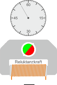
A reluctance motor is a type of electric motor that induces non-permanent magnetic poles on the ferromagnetic rotor. The rotor does not have any windings. It generates torque through magnetic reluctance.

An AC motor is an electric motor driven by an alternating current (AC). The AC motor commonly consists of two basic parts, an outside stator having coils supplied with alternating current to produce a rotating magnetic field, and an inside rotor attached to the output shaft producing a second rotating magnetic field. The rotor magnetic field may be produced by permanent magnets, reluctance saliency, or DC or AC electrical windings.

The rotor is a moving component of an electromagnetic system in the electric motor, electric generator, or alternator. Its rotation is due to the interaction between the windings and magnetic fields which produces a torque around the rotor's axis.
A brushed DC electric motor is an internally commutated electric motor designed to be run from a direct current power source and utilizing an electric brush for contact.

An outrunner is an electric motor having the rotor outside the stator, as though the motor were turned inside out. They are often used in radio-controlled model aircraft.
In electrical engineering, electric machine is a general term for machines using electromagnetic forces, such as electric motors, electric generators, and others. They are electromechanical energy converters: an electric motor converts electricity to mechanical power while an electric generator converts mechanical power to electricity. The moving parts in a machine can be rotating or linear. While transformers are occasionally called "static electric machines", since they do not have moving parts, generally they are not considered "machines", but as electrical devices "closely related" to the electrical machines.

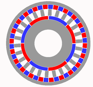
The switched reluctance motor (SRM) is an electric motor that runs by reluctance torque and thus is a subgroup in reluctance motors. Unlike common brushed DC motor types, power is delivered to windings in the stator (case) rather than the rotor. This greatly simplifies mechanical design as power does not have to be delivered to a moving part which eliminates the need for a commutator, but it complicates the electrical design as some sort of switching system needs to be used to deliver power to the different windings. Electronic devices can precisely time the switching of currents, facilitating SRM configurations. Its main drawback is torque ripple. Controller technology that limits torque ripple at low speeds has been demonstrated. Sources disagree on whether it is a type of stepper motor.
A bipolar electric motor is an electric motor with only two poles to its stationary field. They are an example of the simple brushed DC motor, with a commutator. This field may be generated by either a permanent magnet or a field coil.
A magnetic gear resembles the traditional mechanical gear in geometry and function, using magnets instead of teeth. As two opposing magnets approach each other, they repel; when placed on two rings the magnets will act like teeth. As opposed to conventional hard contact backlash in a spur gear, where a gear may rotate freely until in contact with the next gear, the magnetic gear has a springy backlash. As a result magnetic gears are able to apply pressure no matter the relative angle. Although they provide a motion ratio as a traditional gear, such gears work without touching and are immune to wear of mating surfaces, have no noise, and may slip without damage.
In engineering, a solenoid is a device that converts electrical energy to mechanical energy, using an electromagnet formed from a coil of wire. The device creates a magnetic field from electric current, and uses the magnetic field to create linear motion. In electromagnetic technology, a solenoid is an actuator assembly with a sliding ferromagnetic plunger inside the coil. Without power, the plunger extends for part of its length outside the coil; applying power pulls the plunger into the coil. Electromagnets with fixed cores are not considered solenoids. In simple terms, a solenoid converts electrical energy into mechanical work. Typically, it has a multiturn coil of magnet wire surrounded by a frame, which is also a magnetic flux carrier to enhance its efficiency. In engineering, the term may also refer to a variety of transducer devices that convert energy into linear motion, more sophisticated than simple two–position actuators. The term "solenoid" also often refers to a solenoid valve, an integrated device containing an electromechanical solenoid which actuates either a pneumatic or hydraulic valve, or a solenoid switch, which is a specific type of relay that internally uses an electromechanical solenoid to operate an electrical switch; for example, an automobile starter solenoid or linear solenoid. Solenoid bolts, a type of electromechanical locking mechanism, also exist.
Switched reluctance linear motors (SRLMs) are a type of electric machines called linear motors which work based on the principle of a varying magnetic reluctance for force generation. The system can be used in reversed mode and then is called Switched Reluctance Linear Generator. The SRLMs consist of two parts: the active part or primary part and the passive or secondary. The active part contains the windings and defines two main types of LSRMs: transverse and longitudinal. It is longitudinal when the plane that contains the flux lines is parallel to the line of movement and transverse when it is perpendicular. Other classifications are considering the windings totally concentrated in one coil per phase or partially concentrated in two poles per phase or four poles per phase (double-sided). Switched Reluctance motors have been used extensively in clocks and phonograph turntables before, but nowadays, with the rising emphasis on energy efficiency, SR motors are taking more prominent roles in appliances, industrial uses, and commercial and vehicular applications and they are getting traction in the linear applications due to their simplicity, robustness, economic rationality, and high fault tolerance ability as compared with the Linear Synchronous and Linear Induction motors. The SRLM has been researched widely and there are applications of SRLMs and generators for example in wave energy conversion or hyperloop ultra high speed transportation system. One of the main advantages of the SRLM is that it does not require the use of permanent magnets, which are considered a scarce material, so it enables it to be deployed over long distances.