Leak-down tester

Last updated

A leak-down tester is a measuring instrument used to determine the condition of internal combustion engines by introducing compressed air into the cylinder and measuring the rate at which it leaks out.

Compression testing is a crude form of leak-down testing which also includes effects due to compression ratio, valve timing, cranking speed, and other factors. Compression tests should normally be done with all spark plugs removed to maximize cranking speed. Cranking compression is a dynamic test of the actual low-speed pumping action, where peak cylinder pressure is measured and stored.

A compression tester. Motometter compression tester FVM.151991 - 1.jpg
A compression tester.

Leak-down testing is a static test. Leak-down tests cylinder leakage paths. Leak-down primarily tests pistons and rings, seated valve sealing, and the head gasket.

Leak-down will not show valve timing and movement problems, or piston movement related sealing problems. Any test should include both compression and leak-down.

Testing is done on an engine which is not running, and normally with the tested cylinder at top dead center on compression, although testing can be done at other points in the compression and power stroke. Pressure is fed into a cylinder via the spark plug hole and the flow, which represents any leakage from the cylinder, is measured. Leak-down tests tend to rotate the engine, and often require some method of holding the crankshaft in the proper position for each tested cylinder. This can be as simple as a breaker bar on a crankshaft bolt in an automatic transmission vehicle, or leaving a manual transmission vehicle in a high gear with the parking brake locked.

Leakage is given in wholly arbitrary percentages but these “percentages” do not relate to any actual quantity or real dimension. The meaning of the readings is only relative to other tests done with the same tester design. Leak-down readings of up to 20% are usually acceptable. Leakages over 20% generally indicate internal repairs are required. Racing engines would be in the 1-10% range for top performance, although this number can vary. Ideally, a baseline number should be taken on a fresh engine and recorded. The same leakage tester, or the same leakage tester design, can be used to determine wear.

In the United States, FAA specifications [1] state that engines up to 1,000 cu in (16 L) engine displacement require an 0.040 in (1.0 mm) orifice diameter, 0.250 in (6.4 mm) long, 60-degree approach angle. The input pressure is set for 80 psi (550 kPa), and 60 psi (410 kPa) minimum cylinder pressure is the accepted standard.

While the leak-down tester pressurizes the cylinder, the mechanic can listen to various parts to determine where any leak may originate. For example, a leaking exhaust valve will make a hissing noise in the exhaust pipe while a head gasket may cause bubbling in the cooling system.

How it works

This schematic shows the component parts of a typical leak-down tester. The gauge on the right is held at a standard pressure by adjusting the pressure regulator while the gauge on the left shows an example reading of 85, or 15% leakage. Leak down tester.GIF
This schematic shows the component parts of a typical leak-down tester. The gauge on the right is held at a standard pressure by adjusting the pressure regulator while the gauge on the left shows an example reading of 85, or 15% leakage.

A leak-down tester [2] is essentially a miniature flow meter similar in concept to an air flow bench. The measuring element is the restriction orifice and the leakage in the engine is compared to the flow of this orifice. There will be a pressure drop across the orifice and another across any points of leakage in the engine. Since the meter and engine are connected in series, the flow is the same across both. (For example: If the meter was unconnected so that all the air escapes then the reading would be 0, or 100% leakage. Conversely, if there is no leakage there will be no pressure drop across either the orifice or the leak, giving a reading of 100, or 0% leakage).

Gauge meter faces can be numbered 0-100 or 100-0, indicating either 0% at full pressure or 100% at full pressure.

There is no standard regarding the size of the restriction orifice for non-aviation use and that is what leads to differences in readings between leak-down testers generally available from different manufacturers. Most often quoted though is a restriction with a .040in. hole drilled in it. Some poorly designed units do not include a restriction orifice at all, relying on the internal restriction of the regulator, and give much less accurate results. In addition, large engines and small engines will be measured in the same way (compared to the same orifice) but a small leak in a large engine would be a large leak in a small engine. A locomotive engine which gives a leak-down of 10% on a leak-down tester is virtually perfectly sealed while the same tester giving a 10% reading on a model airplane engine indicates a catastrophic leak.

With a non-turbulent .040" orifice, and with a cylinder leakage effective orifice size of .040", leakage would be 50% at any pressure. At higher leakages the orifice can become turbulent, and this makes flow non-linear. Also, leakage paths in cylinders can be turbulent at fairly low flow rates. This makes leakage non-linear with test pressure. Further complicating things, nonstandard restriction orifice sizes will cause different indicated leakage percentages with the same cylinder leakage. Leak down testers are most accurate at low leakage levels, and the exact leakage reading is just a relative indication that can vary significantly between instruments.

Some manufacturers use only a single gauge. In these instruments, the orifice inlet pressure is maintained automatically by the pressure regulator. A single gauge works well as long as leakage flow is much less than regulator flow. Any error in the input pressure will produce a corresponding error in the reading. As a single gauge instrument approaches 100% leakage, the leakage scale error reaches maximum. This may or may not induce significant error, depending on regulator flow and orifice flow. At low and modest leakage percentages, there is little or no difference between single and dual gauges.

In instruments with two gauges the operator manually resets the pressure to 100 after connection to the engine guaranteeing consistent input pressure and greater accuracy.

Most instruments use 100 psi (690 kPa) as the input pressure simply because ordinary 100psi gauges can be used which corresponds to 100% but there is no necessity for that pressure beyond that. Any pressure above 15 psi (100 kPa) will function just as well for measurement purposes although the sound of leaks will not be quite as loud. Besides leakage noise, indicated percentage of leakage will sometimes vary with regulator pressure and orifice size. With 100 psi and a .030" orifice, a given cylinder might show 20% leakage. At 50 psi, the same cylinder might show 30% leakage or 15% leakage with the same orifice. This happens because leakage flow is almost always very turbulent. Because of turbulence and other factors, such as seating pressures, test pressure changes almost always change the effective orifice formed by cylinder leakage paths.

Metering orifice size has a direct effect on leakage percentage.

Generally, a typical automotive engine pressurized to more than 30-40 psi must be locked or it will rotate under test pressure. The exact test pressure tolerated before rotation is highly dependent on connecting rod angle, bore, compression of other cylinders, and friction. There is less tendency to rotate when the piston is at top dead center, especially with small bore engines. Maximum tendency to rotate occurs at about half stroke, when the rod is at right angles to the crankshaft's throw.

Due to the simple construction, many mechanics build their own testers. Homemade instruments can function as well as commercial testers, providing they employ proper orifice sizes, good pressure gauges, and good regulators.

Related Research Articles

Reciprocating engine Engine utilising one or more reciprocating pistons

A reciprocating engine, also often known as a piston engine, is typically a heat engine that uses one or more reciprocating pistons to convert high temperature and high pressure into a rotating motion. This article describes the common features of all types. The main types are: the internal combustion engine, used extensively in motor vehicles; the steam engine, the mainstay of the Industrial Revolution; and the Stirling engine for niche applications. Internal combustion engines are further classified in two ways: either a spark-ignition (SI) engine, where the spark plug initiates the combustion; or a compression-ignition (CI) engine, where the air within the cylinder is compressed, thus heating it, so that the heated air ignites fuel that is injected then or earlier.

Valve Flow control device

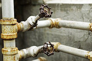
A valve is a device or natural object that regulates, directs or controls the flow of a fluid by opening, closing, or partially obstructing various passageways. Valves are technically fittings, but are usually discussed as a separate category. In an open valve, fluid flows in a direction from higher pressure to lower pressure. The word is derived from the Latin valva, the moving part of a door, in turn from volvere, to turn, roll.

Self-contained breathing apparatus Breathing gas supply system carried by the user

A self-contained breathing apparatus (SCBA), sometimes referred to as a compressed air breathing apparatus (CABA) or simply breathing apparatus (BA), is a device worn to provide breathable air in an atmosphere that is immediately dangerous to life or health. They are typically used in firefighting and industry. The term self-contained means that the SCBA is not dependent on a remote supply of breathing gas. If designed for use under water, it is also known as a Scuba set. When not used underwater, they are sometimes called industrial breathing sets. Unofficial names include air pack, air tank, oxygen cylinder or simply pack, which are mostly used in firefighting.

Engine tuning

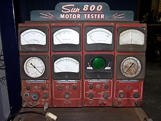
Engine tuning is the adjustment or modification of the internal combustion engine or Engine Control Unit (ECU) to yield optimal performance and increase the engine's power output, economy, or durability. These goals may be mutually exclusive; an engine may be de-tuned with respect to output power in exchange for better economy or longer engine life due to lessened stress on engine components.

Fuel pump Pump

A fuel pump is a component in motor vehicles that transfers liquid from the fuel tank to the carburetor or fuel injector of the internal combustion engine.

Diving cylinder Cylinder to supply breathing gas for divers

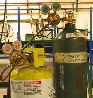
A diving cylinder or diving gas cylinder is a gas cylinder used to store and transport high pressure gas used in diving operations. This may be breathing gas used with a scuba set, in which case the cylinder may also be referred to as a scuba cylinder, scuba tank or diving tank. When used for an emergency gas supply for surface supplied diving or scuba, it may be referred to as a bailout cylinder or bailout bottle. It may also be used for surface-supplied diving or as decompression gas. A diving cylinder may also be used to supply inflation gas for a dry suit or buoyancy compensator. Cylinders provide gas to the diver through the demand valve of a diving regulator or the breathing loop of a diving rebreather.

Diving regulator Mechanism that controls the pressure of a breathing gas supply for diving

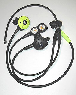
A diving regulator is a pressure regulator that controls the pressure of breathing gas for diving. The most commonly recognised application is to reduce pressurized breathing gas to ambient pressure and deliver it to the diver, but there are also other types of gas pressure regulator used for diving applications. The gas may be air or one of a variety of specially blended breathing gases. The gas may be supplied from a scuba cylinder carried by the diver or via a hose from a compressor or high-pressure storage cylinders at the surface in surface-supplied diving. A gas pressure regulator has one or more valves in series which reduce pressure from the source, and use the downstream pressure as feedback to control the delivered pressure, or the upstream pressure as feedback to prevent excessive flow rates, lowering the pressure at each stage.

Volumetric efficiency (VE) in internal combustion engine engineering is defined as the ratio of the mass density of the air-fuel mixture drawn into the cylinder at atmospheric pressure to the mass density of the same volume of air in the intake manifold. The term is also used in other engineering contexts, such as hydraulic pumps and electronic components.

Diving air compressor Machine used to compress breathing air for use by underwater divers

A diving air compressor is a gas compressor that can provide breathing air directly to a surface-supplied diver, or fill diving cylinders with high-pressure air pure enough to be used as a breathing gas. A low pressure diving air compressor usually has a delivery pressure of up to 30 bar, which is regulated to suit the depth of the dive. A high pressure diving compressor has a delivery pressure which is usually over 150 bar, and is commonly between 200 and 300 bar. The pressure is limited by an overpressure valve which may be adjustable.

Engine braking occurs when the retarding forces within an engine are used to slow down a motor vehicle, as opposed to using additional external braking mechanisms such as friction brakes or magnetic brakes.

Hydraulic machinery Type of machine that uses liquid fluid power to perform work

Hydraulic machines use liquid fluid power to perform work. Heavy construction vehicles are a common example. In this type of machine, hydraulic fluid is pumped to various hydraulic motors and hydraulic cylinders throughout the machine and becomes pressurized according to the resistance present. The fluid is controlled directly or automatically by control valves and distributed through hoses, tubes, or pipes.

An exhaust brake is a means of slowing a diesel engine by closing off the exhaust path from the engine, causing the exhaust gases to be compressed in the exhaust manifold, and in the cylinder. Since the exhaust is being compressed, and there is no fuel being applied, the engine slows down the vehicle. The amount of negative torque generated is usually directly proportional to the back pressure of the engine.

MAP sensor

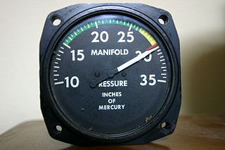
The manifold absolute pressure sensor is one of the sensors used in an internal combustion engine's electronic control system.

Air flow bench Device for testing internal aerodynamics of engine parts

An air flow bench is a device used for testing the internal aerodynamic qualities of an engine component and is related to the more familiar wind tunnel.

Pressure regulator Control valve that maintains the pressure of a fluid or gas

A pressure regulator is a valve that controls the pressure of a fluid or gas to a desired value, using negative feedback from the controlled pressure. Regulators are used for gases and liquids, and can be an integral device with a pressure setting, a restrictor and a sensor all in the one body, or consist of a separate pressure sensor, controller and flow valve.

A shutdown valve is an actuated valve designed to stop the flow of a hazardous fluid upon the detection of a dangerous event. This provides protection against possible harm to people, equipment or the environment. Shutdown valves form part of a safety instrumented system. The process of providing automated safety protection upon the detection of a hazardous event is called functional safety.

Oil pump (internal combustion engine) Internal combustion engine part that circulates engine oil under pressure

The oil pump is an internal combustion engine part that circulates engine oil under pressure to the rotating bearings, the sliding pistons and the camshaft of the engine. This lubricates the bearings, allows the use of higher-capacity fluid bearings and also assists in cooling the engine.

Scuba cylinder valve Valve controlling flow of breathing gas into and out of a scuba cylinder

A scuba cylinder valve or pillar valve is a high pressure manually operated screw-down shut off valve fitted to the neck of a scuba cylinder to control breathing gas flow to and from the pressure vessel and to provide a connection with the scuba regulator or filling whip. Cylinder valves are usually machined from brass and finished with a protective and decorative layer of chrome plating. A metal or plastic dip tube or valve snorkel screwed into the bottom of the valve extends into the cylinder to reduce the risk of liquid or particulate contaminants in the cylinder getting into the gas passages when the cylinder is inverted, and blocking or jamming the regulator.

Mechanism of diving regulators How the mechanisms of diving regulators work

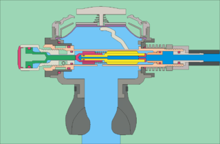
The mechanism of diving regulators is the arrangement of components and function of gas pressure regulators used in the systems which supply breathing gases for underwater diving. Both free-flow and demand regulators use mechanical feedback of the downstream pressure to control the opening of a valve which controls gas flow from the upstream, high-pressure side, to the downstream, low-pressure side of each stage. Flow capacity must be sufficient to allow the downstream pressure to be maintained at maximum demand, and sensitivity must be appropriate to deliver maximum required flow rate with a small variation in downstream pressure, and for a large variation in supply pressure, without instability of flow. Open circuit scuba regulators must also deliver against a variable ambient pressure. They must be robust and reliable, as they are life-support equipment which must function in the relatively hostile seawater environment, and the human interface must be comfortable over periods of several hours.

References

  1. Advisory Circular 43.13-1B, chapter eight
  2. "Leak Down Tester". Czok.{{cite web}}: CS1 maint: url-status (link)