
Diffraction is the interference or bending of waves around the corners of an obstacle or through an aperture into the region of geometrical shadow of the obstacle/aperture. The diffracting object or aperture effectively becomes a secondary source of the propagating wave. Italian scientist Francesco Maria Grimaldi coined the word diffraction and was the first to record accurate observations of the phenomenon in 1660.

In optics, the refractive index of an optical medium is a dimensionless number that gives the indication of the light bending ability of that medium.
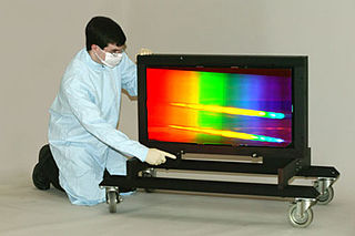
In optics, a diffraction grating is an optical grating with a periodic structure that diffracts light into several beams traveling in different directions. The emerging coloration is a form of structural coloration. The directions or diffraction angles of these beams depend on the wave (light) incident angle to the diffraction grating, the spacing or distance between adjacent diffracting elements on the grating, and the wavelength of the incident light. The grating acts as a dispersive element. Because of this, diffraction gratings are commonly used in monochromators and spectrometers, but other applications are also possible such as optical encoders for high-precision motion control and wavefront measurement.
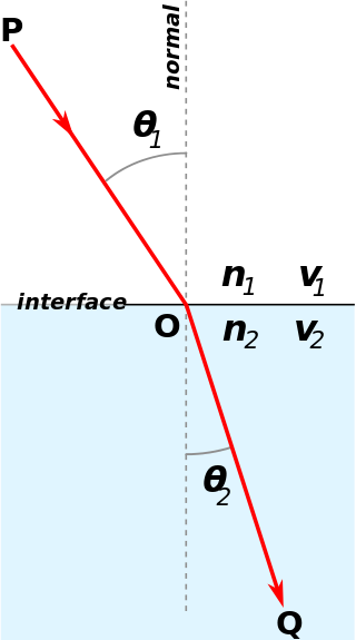
Snell's law is a formula used to describe the relationship between the angles of incidence and refraction, when referring to light or other waves passing through a boundary between two different isotropic media, such as water, glass, or air. In optics, the law is used in ray tracing to compute the angles of incidence or refraction, and in experimental optics to find the refractive index of a material. The law is also satisfied in meta-materials, which allow light to be bent "backward" at a negative angle of refraction with a negative refractive index.

Angular resolution describes the ability of any image-forming device such as an optical or radio telescope, a microscope, a camera, or an eye, to distinguish small details of an object, thereby making it a major determinant of image resolution. It is used in optics applied to light waves, in antenna theory applied to radio waves, and in acoustics applied to sound waves. The colloquial use of the term "resolution" sometimes causes confusion; when an optical system is said to have a high resolution or high angular resolution, it means that the perceived distance, or actual angular distance, between resolved neighboring objects is small. The value that quantifies this property, θ, which is given by the Rayleigh criterion, is low for a system with a high resolution. The closely related term spatial resolution refers to the precision of a measurement with respect to space, which is directly connected to angular resolution in imaging instruments. The Rayleigh criterion shows that the minimum angular spread that can be resolved by an image forming system is limited by diffraction to the ratio of the wavelength of the waves to the aperture width. For this reason, high resolution imaging systems such as astronomical telescopes, long distance telephoto camera lenses and radio telescopes have large apertures.
Fourier optics is the study of classical optics using Fourier transforms (FTs), in which the waveform being considered is regarded as made up of a combination, or superposition, of plane waves. It has some parallels to the Huygens–Fresnel principle, in which the wavefront is regarded as being made up of a combination of spherical wavefronts whose sum is the wavefront being studied. A key difference is that Fourier optics considers the plane waves to be natural modes of the propagation medium, as opposed to Huygens–Fresnel, where the spherical waves originate in the physical medium.
In physics and chemistry, Bragg's law, Wulff–Bragg's condition or Laue–Bragg interference, a special case of Laue diffraction, gives the angles for coherent scattering of waves from a large crystal lattice. It encompasses the superposition of wave fronts scattered by lattice planes, leading to a strict relation between wavelength and scattering angle, or else to the wavevector transfer with respect to the crystal lattice. Such law had initially been formulated for X-rays upon crystals. However, it applies to all sorts of quantum beams, including neutron and electron waves at atomic distances if there are a large number of atoms, as well as visible light with artificial periodic microscale lattices.

In optics, the Airy disk and Airy pattern are descriptions of the best-focused spot of light that a perfect lens with a circular aperture can make, limited by the diffraction of light. The Airy disk is of importance in physics, optics, and astronomy.
In optics, the Fraunhofer diffraction equation is used to model the diffraction of waves when plane waves are incident on a diffracting object, and the diffraction pattern is viewed at a sufficiently long distance from the object, and also when it is viewed at the focal plane of an imaging lens. In contrast, the diffraction pattern created near the diffracting object and is given by the Fresnel diffraction equation.

The shearing interferometer is an extremely simple means to observe interference and to use this phenomenon to test the collimation of light beams, especially from laser sources which have a coherence length which is usually significantly longer than the thickness of the shear plate so that the basic condition for interference is fulfilled.
Fluorescence interference contrast (FLIC) microscopy is a microscopic technique developed to achieve z-resolution on the nanometer scale.

In optics, a dispersive prism is an optical prism that is used to disperse light, that is, to separate light into its spectral components. Different wavelengths (colors) of light will be deflected by the prism at different angles. This is a result of the prism material's index of refraction varying with wavelength (dispersion). Generally, longer wavelengths (red) undergo a smaller deviation than shorter wavelengths (blue). The dispersion of white light into colors by a prism led Sir Isaac Newton to conclude that white light consisted of a mixture of different colors.

Acousto-optics is a branch of physics that studies the interactions between sound waves and light waves, especially the diffraction of laser light by ultrasound through an ultrasonic grating.
Volume holograms are holograms where the thickness of the recording material is much larger than the light wavelength used for recording. In this case diffraction of light from the hologram is possible only as Bragg diffraction, i.e., the light has to have the right wavelength (color) and the wave must have the right shape. Volume holograms are also called thick holograms or Bragg holograms.
Free spectral range (FSR) is the spacing in optical frequency or wavelength between two successive reflected or transmitted optical intensity maxima or minima of an interferometer or diffractive optical element.
A blazed grating – also called echelette grating – is a special type of diffraction grating. It is optimized to achieve maximum grating efficiency in a given diffraction order. For this purpose, maximum optical power is concentrated in the desired diffraction order while the residual power in the other orders is minimized. Since this condition can only exactly be achieved for one wavelength, it is specified for which blaze wavelength the grating is optimized. The direction in which maximum efficiency is achieved is called the blaze angle and is the third crucial characteristic of a blazed grating directly depending on blaze wavelength and diffraction order.
An ultrasonic grating is a type of diffraction grating produced by the interference of ultrasonic waves in a medium, which alters the physical properties of the medium in a grid-like pattern. The term acoustic grating is a more general term that includes operation at audible frequencies.

Thin-film interference is a natural phenomenon in which light waves reflected by the upper and lower boundaries of a thin film interfere with one another, either enhancing or reducing the reflected light. When the thickness of the film is an odd multiple of one quarter-wavelength of the light on it, the reflected waves from both surfaces interfere to cancel each other. Since the wave cannot be reflected, it is completely transmitted instead. When the thickness is a multiple of a half-wavelength of the light, the two reflected waves reinforce each other, increasing the reflection and reducing the transmission. Thus when white light, which consists of a range of wavelengths, is incident on the film, certain wavelengths (colors) are intensified while others are attenuated. Thin-film interference explains the multiple colors seen in light reflected from soap bubbles and oil films on water. It is also the mechanism behind the action of antireflection coatings used on glasses and camera lenses. If the thickness of the film is much larger than the coherence length of the incident light, then the interference pattern will be washed out due to the linewidth of the light source.
Holographic optical element (HOE) is an optical component (mirror, lens, directional diffuser, etc.) that produces holographic images using principles of diffraction. HOE is most commonly used in transparent displays, 3D imaging, and certain scanning technologies. The shape and structure of the HOE is dependent on the piece of hardware it is needed for, and the coupled wave theory is a common tool used to calculate the diffraction efficiency or grating volume that helps with the design of an HOE. Early concepts of the holographic optical element can be traced back to the mid-1900s, coinciding closely with the start of holography coined by Dennis Gabor. The application of 3D visualization and displays is ultimately the end goal of the HOE; however, the cost and complexity of the device has hindered the rapid development toward full 3D visualization. The HOE is also used in the development of augmented reality(AR) by companies such as Google with Google Glass or in research universities that look to utilize HOEs to create 3D imaging without the use of eye-wear or head-wear. Furthermore, the ability of the HOE to allow for transparent displays have caught the attention of the US military in its development of better head-up displays (HUD) which is used to display crucial information for aircraft pilots.
A compound prism is a set of multiple triangular prism elements placed in contact, and often cemented together to form a solid assembly. The use of multiple elements gives several advantages to an optical designer:


