Related Research Articles

An amplifier, electronic amplifier or (informally) amp is an electronic device that can increase the power of a signal. It is a two-port electronic circuit that uses electric power from a power supply to increase the amplitude of a signal applied to its input terminals, producing a proportionally greater amplitude signal at its output. The amount of amplification provided by an amplifier is measured by its gain: the ratio of output voltage, current, or power to input. An amplifier is a circuit that has a power gain greater than one.

An operational amplifier is a DC-coupled high-gain electronic voltage amplifier with a differential input and, usually, a single-ended output. In this configuration, an op amp produces an output potential that is typically 100,000 times larger than the potential difference between its input terminals. The operational amplifier traces its origin and name to analog computers, where they were used to perform mathematical operations in linear, non-linear, and frequency-dependent circuits.
The Hartley oscillator is an electronic oscillator circuit in which the oscillation frequency is determined by a tuned circuit consisting of capacitors and inductors, that is, an LC oscillator. The circuit was invented in 1915 by American engineer Ralph Hartley. The distinguishing feature of the Hartley oscillator is that the tuned circuit consists of a single capacitor in parallel with two inductors in series, and the feedback signal needed for oscillation is taken from the center connection of the two inductors.

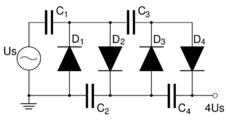
A voltage multiplier is an electrical circuit that converts AC electrical power from a lower voltage to a higher DC voltage, typically using a network of capacitors and diodes.

A push–pull amplifier is a type of electronic circuit that uses a pair of active devices that alternately supply current to, or absorb current from, a connected load. This kind of amplifier can enhance both the load capacity and switching speed.
In signal processing, when describing a periodic function in the time domain, the DC bias, DC component, DC offset, or DC coefficient is the mean amplitude of the waveform. If the mean amplitude is zero, there is no DC bias. A waveform with no DC bias is known as a DC balanced or DC free waveform.

The Cockcroft–Walton (CW) generator, or multiplier, is an electric circuit that generates a high DC voltage from a low-voltage AC or pulsing DC input. It was named after the British and Irish physicists John Douglas Cockcroft and Ernest Thomas Sinton Walton, who in 1932 used this circuit design to power their particle accelerator, performing the first artificial nuclear disintegration in history. They used this voltage multiplier cascade for most of their research, which in 1951 won them the Nobel Prize in Physics for "Transmutation of atomic nuclei by artificially accelerated atomic particles". The circuit was discovered in 1919, by Heinrich Greinacher, a Swiss physicist. For this reason, this doubler cascade is sometimes also referred to as the Greinacher multiplier. Cockcroft–Walton circuits are still used in particle accelerators. They also are used in everyday electronic devices that require high voltages, such as X-ray machines, microwave ovens and photocopiers.

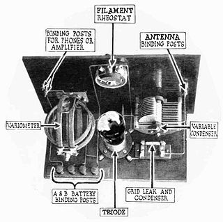
A grid leak detector is an electronic circuit that demodulates an amplitude modulated alternating current and amplifies the recovered modulating voltage. The circuit utilizes the non-linear cathode to control grid conduction characteristic and the amplification factor of a vacuum tube. Invented by Lee De Forest around 1912, it was used as the detector (demodulator) in the first vacuum tube radio receivers until the 1930s.
A radio transmitter or just transmitter is an electronic device which produces radio waves with an antenna. Radio waves are electromagnetic waves with frequencies between about 30 Hz and 300 GHz. The transmitter itself generates a radio frequency alternating current, which is applied to the antenna. When excited by this alternating current, the antenna radiates radio waves. Transmitters are necessary parts of all systems that use radio: radio and television broadcasting, cell phones, wireless networks, radar, two way radios like walkie talkies, radio navigation systems like GPS, remote entry systems, among numerous other uses.
In electronics, direct coupling or DC coupling is the transfer of electrical energy by means of physical contact via a conductive medium, in contrast to inductive coupling and capacitive coupling. It is a way of interconnecting two circuits such that, in addition to transferring the AC signal, the first circuit also provides DC bias to the second. Thus, DC blocking capacitors are not used or needed to interconnect the circuits. Conductive coupling passes the full spectrum of frequencies including direct current.
A direct-coupled amplifier or DC amplifier is a type of amplifier in which the output of one stage of the amplifier is coupled to the input of the next stage in such a way as to permit signals with zero frequency, also referred to as direct current, to pass from input to output. This is an application of the more general direct coupling. It was invented by Harold J Paz and Francis P. Keiper Jr. in 1955. It displaced the triode vacuum tube amplifier designed by Lee de Forest. Almost all vacuum tube circuit designs are now replaced with direct coupled transistor circuit design. It is the first transistor amplifier design that did not include coupling capacitors. The direct-coupled amplifier allowed analog circuits to be built smaller with the elimination of coupling capacitors and removed the lower frequency limitation that is dependent on capacitors.

A multistage amplifier is an electronic amplifier consisting of two or more single-stage amplifiers connected together. In this context, a single stage is an amplifier containing only a single transistor or other active device. The most common reason for using multiple stages is to increase the gain of the amplifier in applications where the input signal is very small, for instance in radio receivers. In these applications a single stage has insufficient gain by itself. In some designs it is possible to obtain more desirable values of other parameters such as input resistance and output resistance.
A bias tee is a three-port network used for setting the DC bias point of some electronic components without disturbing other components. The bias tee is a diplexer. The low-frequency port is used to set the bias; the high-frequency port passes the radio-frequency signals but blocks the biasing levels; the combined port connects to the device, which sees both the bias and RF. It is called a tee because the 3 ports are often arranged in the shape of a T.
In the field of electronics, a technique where part of the output of a system is used at startup can be described as bootstrapping.

The single-ended primary-inductor converter (SEPIC) is a type of DC/DC converter that allows the electrical potential (voltage) at its output to be greater than, less than, or equal to that at its input. The output of the SEPIC is controlled by the duty cycle of the control switch (S1).

In electronics, biasing is the setting of DC operating conditions of an active device in an amplifier. Many electronic devices, such as diodes, transistors and vacuum tubes, whose function is processing time-varying (AC) signals, also require a steady (DC) current or voltage at their terminals to operate correctly. This current or voltage is called bias. The AC signal applied to them is superposed on this DC bias current or voltage.
Technical specifications and detailed information on the valve audio amplifier, including its development history.

Bipolar transistors must be properly biased to operate correctly. In circuits made with individual devices, biasing networks consisting of resistors are commonly employed. Much more elaborate biasing arrangements are used in integrated circuits, for example, bandgap voltage references and current mirrors. The voltage divider configuration achieves the correct voltages by the use of resistors in certain patterns. By selecting the proper resistor values, stable current levels can be achieved that vary only little over temperature and with transistor properties such as β.
Output transformerless (OTL) is a type of vacuum tube audio power amplifier, which omits an output transformer for the purpose of greater linearity and fidelity. Conventional vacuum tube amplifier designs rely upon an output transformer to couple the amplifier's output stage to the loudspeaker. Instead, OTLs use one of two primary methods for output stage coupling: direct coupling (DC) or capacitive coupling (AC).
In electronics, power amplifier classes are letter symbols applied to different power amplifier types. The class gives a broad indication of an amplifier's characteristics and performance. The classes are related to the time period that the active amplifier device is passing current, expressed as a fraction of the period of a signal waveform applied to the input. A class A amplifier is conducting through all the period of the signal; Class B only for one-half the input period, class C for much less than half the input period. A Class D amplifier operates its output device in a switching manner; the fraction of the time that the device is conducting is adjusted so a pulse-width modulation output is obtained from the stage.
References
- ↑ OCL Amplifier Explainedhomemade-circuits.Received on January 19, 2023