In cryptography, a block cipher is a deterministic algorithm operating on fixed-length groups of bits, called blocks. Block ciphers are specified elementary components in the design of many cryptographic protocols and are widely used to encrypt large amounts of data, including in data exchange protocols. A block cipher uses blocks as an unvarying transformation.

Frame Relay is a standardized wide area network (WAN) technology that specifies the physical and data link layers of digital telecommunications channels using a packet switching methodology. Originally designed for transport across Integrated Services Digital Network (ISDN) infrastructure, it may be used today in the context of many other network interfaces.
A network switch is networking hardware that connects devices on a computer network by using packet switching to receive and forward data to the destination device.

In electronics and telecommunications, a crossbar switch is a collection of switches arranged in a matrix configuration. A crossbar switch has multiple input and output lines that form a crossed pattern of interconnecting lines between which a connection may be established by closing a switch located at each intersection, the elements of the matrix. Originally, a crossbar switch consisted literally of crossing metal bars that provided the input and output paths. Later implementations achieved the same switching topology in solid-state electronics. The crossbar switch is one of the principal telephone exchange architectures, together with a rotary switch, memory switch, and a crossover switch.
An adder, or summer, is a digital circuit that performs addition of numbers. In many computers and other kinds of processors adders are used in the arithmetic logic units (ALUs). They are also used in other parts of the processor, where they are used to calculate addresses, table indices, increment and decrement operators and similar operations.
LIN is a serial network protocol used for communication between components in vehicles. It is a single wire, serial network protocol that supports communications up to 19.2 Kbit/s at a bus length of 40 meters. The need for a cheap serial network arose as the technologies and the facilities implemented in the car grew, while the CAN bus was too expensive to implement for every component in the car. European car manufacturers started using different serial communication technologies, which led to compatibility problems.

A Medium Attachment Unit (MAU) is a transceiver which converts signals on an Ethernet cable to and from Attachment Unit Interface (AUI) signals.
In computer architecture, a transport triggered architecture (TTA) is a kind of processor design in which programs directly control the internal transport buses of a processor. Computation happens as a side effect of data transports: writing data into a triggering port of a functional unit triggers the functional unit to start a computation. This is similar to what happens in a systolic array. Due to its modular structure, TTA is an ideal processor template for application-specific instruction set processors (ASIP) with customized datapath but without the inflexibility and design cost of fixed function hardware accelerators.
XOR gate is a digital logic gate that gives a true output when the number of true inputs is odd. An XOR gate implements an exclusive or from mathematical logic; that is, a true output results if one, and only one, of the inputs to the gate is true. If both inputs are false (0/LOW) or both are true, a false output results. XOR represents the inequality function, i.e., the output is true if the inputs are not alike otherwise the output is false. A way to remember XOR is "must have one or the other but not both".
In computer networking, a port or port number is a number assigned to uniquely identify a connection endpoint and to direct data to a specific service. At the software level, within an operating system, a port is a logical construct that identifies a specific process or a type of network service. A port at the software level is identified for each transport protocol and address combination by the port number assigned to it. The most common transport protocols that use port numbers are the Transmission Control Protocol (TCP) and the User Datagram Protocol (UDP); those port numbers are 16-bit unsigned numbers.
In the field of telecommunications, a Clos network is a kind of multistage circuit-switching network which represents a theoretical idealization of practical, multistage switching systems. It was invented by Edson Erwin in 1938 and first formalized by the American engineer Charles Clos in 1952.
The Number One Electronic Switching System (1ESS) was the first large-scale stored program control (SPC) telephone exchange or electronic switching system in the Bell System. It was manufactured by Western Electric and first placed into service in Succasunna, New Jersey, in May 1965. The switching fabric was composed of a reed relay matrix controlled by wire spring relays which in turn were controlled by a central processing unit (CPU).
The GTD-5 EAX is the Class 5 telephone switch developed by GTE Automatic Electric Laboratories. This digital central office telephone circuit switching system is used in the former GTE service areas and by many smaller telecommunications service providers.
Multistage interconnection networks (MINs) are a class of high-speed computer networks usually composed of processing elements (PEs) on one end of the network and memory elements (MEs) on the other end, connected by switching elements (SEs). The switching elements themselves are usually connected to each other in stages, hence the name.

In computing, an arithmetic logic unit (ALU) is a combinational digital circuit that performs arithmetic and bitwise operations on integer binary numbers. This is in contrast to a floating-point unit (FPU), which operates on floating point numbers. It is a fundamental building block of many types of computing circuits, including the central processing unit (CPU) of computers, FPUs, and graphics processing units (GPUs).
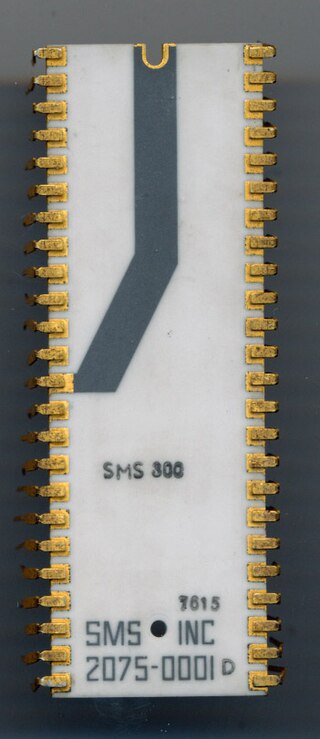
The 8X300 is a microprocessor produced and marketed by Signetics starting 1976 as a second source for the SMS 300 by Scientific Micro Systems, Inc. Although SMS developed the SMS 300, Signetics was the sole manufacturer of this product line. In 1978 Signetics purchased the rights to the SMS 300 series and renamed it 8X300.
In computer networking, a flit is a link-level atomic piece that forms a network packet or stream. The first flit, called the header flit holds information about this packet's route and sets up the routing behavior for all subsequent flits associated with the packet. The header flit is followed by zero or more body flits, containing the actual payload of data. The final flit, called the tail flit, performs some book keeping to close the connection between the two nodes.
The STC104 switch, also known as the C104 switch in its early phases, is an asynchronous packet-routing chip that was designed for building high-performance point-to-point computer communication networks. It was developed by INMOS in the 1990s and was the first example of a general-purpose production packet routing chip. It was also the first routing chip to implement wormhole routing, to decouple packet size from the flow-control protocol, and to implement interval and two-phase randomized routing.

In computer networking, hypercube networks are a type of network topology used to connect multiple processors with memory modules and accurately route data. Hypercube networks consist of 2m nodes, which form the vertices of squares to create an internetwork connection. A hypercube is basically a multidimensional mesh network with two nodes in each dimension. Due to similarity, such topologies are usually grouped into a k-ary d-dimensional mesh topology family, where d represents the number of dimensions and k represents the number of nodes in each dimension.

A butterfly network is a technique to link multiple computers into a high-speed network. This form of multistage interconnection network topology can be used to connect different nodes in a multiprocessor system. The interconnect network for a shared memory multiprocessor system must have low latency and high bandwidth unlike other network systems, like local area networks (LANs) or internet for three reasons:
