
An amplifier, electronic amplifier or (informally) amp is an electronic device that can increase the power of a signal. It is a two-port electronic circuit that uses electric power from a power supply to increase the amplitude of a signal applied to its input terminals, producing a proportionally greater amplitude signal at its output. The amount of amplification provided by an amplifier is measured by its gain: the ratio of output voltage, current, or power to input. An amplifier is a circuit that has a power gain greater than one.
Linear filters process time-varying input signals to produce output signals, subject to the constraint of linearity. This results from systems composed solely of components classified as having a linear response. Most filters implemented in analog electronics, in digital signal processing, or in mechanical systems are classified as causal, time invariant, and linear signal processing filters.
In engineering, a transfer function of an electronic or control system component is a mathematical function which theoretically models the device's output for each possible input. In its simplest form, this function is a two-dimensional graph of an independent scalar input versus the dependent scalar output, called a transfer curve or characteristic curve. Transfer functions for components are used to design and analyze systems assembled from components, particularly using the block diagram technique, in electronics and control theory.
Distortion is the alteration of the original shape of something. In communications and electronics it means the alteration of the waveform of an information-bearing signal, such as an audio signal representing sound or a video signal representing images, in an electronic device or communication channel.
In signal processing, group delay is the time delay of the amplitude envelopes of the various sinusoidal components of a signal through a device under test, and is a function of frequency for each component. Phase delay, in contrast, is the time delay of the phase as opposed to the time delay of the amplitude envelope.
Frequency response is the quantitative measure of the output spectrum of a system or device in response to a stimulus, and is used to characterize the dynamics of the system. It is a measure of magnitude and phase of the output as a function of frequency, in comparison to the input. In simplest terms, if a sine wave is injected into a system at a given frequency, a linear system will respond at that same frequency with a certain magnitude and a certain phase angle relative to the input. Also for a linear system, doubling the amplitude of the input will double the amplitude of the output. In addition, if the system is time-invariant, then the frequency response also will not vary with time. Thus for LTI systems, the frequency response can be seen as applying the system's transfer function to a purely imaginary number argument representing the frequency of the sinusoidal excitation.

An envelope detector is an electronic circuit that takes a (relatively) high-frequency amplitude modulated signal as input and provides an output which is the envelope of the original signal.
Analog signal processing is a type of signal processing conducted on continuous analog signals by some analog means. "Analog" indicates something that is mathematically represented as a set of continuous values. This differs from "digital" which uses a series of discrete quantities to represent signal. Analog values are typically represented as a voltage, electric current, or electric charge around components in the electronic devices. An error or noise affecting such physical quantities will result in a corresponding error in the signals represented by such physical quantities.

An active filter is a type of analog circuit implementing an electronic filter using active components, typically an amplifier. Amplifiers included in a filter design can be used to improve the cost, performance and predictability of a filter.
In electronics engineering, frequency compensation is a technique used in amplifiers, and especially in amplifiers employing negative feedback. It usually has two primary goals: To avoid the unintentional creation of positive feedback, which will cause the amplifier to oscillate, and to control overshoot and ringing in the amplifier's step response. It is also used extensively to improve the bandwidth of single pole systems.
Linear electronic oscillator circuits, which generate a sinusoidal output signal, are composed of an amplifier and a frequency selective element, a filter. A linear oscillator circuit which uses an RC network, a combination of resistors and capacitors, for its frequency selective part is called an RC oscillator.

A lock-in amplifier is a type of amplifier that can extract a signal with a known carrier wave from an extremely noisy environment. Depending on the dynamic reserve of the instrument, signals up to 1 million times smaller than noise components, potentially fairly close by in frequency, can still be reliably detected. It is essentially a homodyne detector followed by low-pass filter that is often adjustable in cut-off frequency and filter order. Whereas traditional lock-in amplifiers use analog frequency mixers and RC filters for the demodulation, state-of-the-art instruments have both steps implemented by fast digital signal processing, for example, on an FPGA. Usually sine and cosine demodulation is performed simultaneously, which is sometimes also referred to as dual-phase demodulation. This allows the extraction of the in-phase and the quadrature component that can then be transferred into polar coordinates, i.e. amplitude and phase, or further processed as real and imaginary part of a complex number.
A television transmitter is a transmitter that is used for terrestrial (over-the-air) television broadcasting. It is an electronic device that radiates radio waves that carry a video signal representing moving images, along with a synchronized audio channel, which is received by television receivers belonging to a public audience, which display the image on a screen. A television transmitter, together with the broadcast studio which originates the content, is called a television station. Television transmitters must be licensed by governments, and are restricted to a certain frequency channel and power level. They transmit on frequency channels in the VHF and UHF bands.

Moogerfooger is the trademark for a series of analog effects pedals manufactured by Moog Music. There are currently eight different pedals produced; however, one of these models is designed for processing control voltages rather than audio signal. A sixth model, the Analog Delay, was released in a limited edition of 1000 units and has become a collector's item.
In electronics, motorboating is a type of low frequency parasitic oscillation that sometimes occurs in audio and radio equipment and often manifests itself as a sound similar to an idling motorboat engine, a "put-put-put", in audio output from speakers or earphones. It is a problem encountered particularly in radio transceivers and older vacuum tube audio systems, guitar amplifiers, PA systems and is caused by some type of unwanted feedback in the circuit. The amplifying devices in audio and radio equipment are vulnerable to a variety of feedback problems, which can cause distinctive noise in the output. The term motorboating is applied to oscillations whose frequency is below the range of hearing, from 1 to 10 hertz, so the individual oscillations are heard as pulses. Sometimes the oscillations can even be seen visually as the woofer cones in speakers slowly moving in and out.
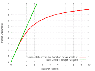
Gain compression is a reduction in "differential" or "slope" gain caused by nonlinearity of the transfer function of the amplifying device. This nonlinearity may be caused by heat due to power dissipation or by overdriving the active device beyond its linear region. It is a large-signal phenomenon of circuits.

In radio, a detector is a device or circuit that extracts information from a modulated radio frequency current or voltage. The term dates from the first three decades of radio (1888-1918). Unlike modern radio stations which transmit sound on an uninterrupted carrier wave, early radio stations transmitted information by radiotelegraphy. The transmitter was switched on and off to produce long or short periods of radio waves, spelling out text messages in Morse code. Therefore, early radio receivers had only to distinguish between the presence or absence of a radio signal. The device that performed this function in the receiver circuit was called a detector. A variety of different detector devices, such as the coherer, electrolytic detector, magnetic detector and the crystal detector, were used during the wireless telegraphy era until superseded by vacuum tube technology.
An all-pass filter is a signal processing filter that passes all frequencies equally in gain, but changes the phase relationship among various frequencies. Most types of filter reduce the amplitude of the signal applied to it for some values of frequency, whereas the all-pass filter allows all frequencies through without changes in level.

A phase splitter is a device that separates a signal into multiple phases.
Differential gain is a kind of linearity distortion which affects the color saturation in TV broadcasting.


