
An amplifier, electronic amplifier or (informally) amp is an electronic device that can increase the magnitude of a signal. A power amplifier is similarly used to deliver output power, controlled by an input signal. It is a two-port electronic circuit that uses electric power from a power supply to increase the amplitude of a signal applied to its input terminals, producing a proportionally greater amplitude signal at its output. The amount of amplification provided by an amplifier is measured by its gain: the ratio of output voltage, current, or power to input. An amplifier is a circuit that has a power gain greater than one.

An operational amplifier is a DC-coupled high-gain electronic voltage amplifier with a differential input and, usually, a single-ended output. In this configuration, an op amp produces an output potential that is typically 100,000 times larger than the potential difference between its input terminals. The operational amplifier traces its origin and name to analog computers, where they were used to perform mathematical operations in linear, non-linear, and frequency-dependent circuits.

In electronics, a comparator is a device that compares two voltages or currents and outputs a digital signal indicating which is larger. It has two analog input terminals and and one binary digital output . The output is ideally
Transistor–transistor logic (TTL) is a logic family built from bipolar junction transistors. Its name signifies that transistors perform both the logic function and the amplifying function, as opposed to earlier resistor–transistor logic (RTL) and diode–transistor logic (DTL).
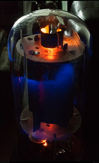
A valve amplifier or tube amplifier is a type of electronic amplifier that uses vacuum tubes to increase the amplitude or power of a signal. Low to medium power valve amplifiers for frequencies below the microwaves were largely replaced by solid state amplifiers in the 1960s and 1970s. Valve amplifiers can be used for applications such as guitar amplifiers, satellite transponders such as DirecTV and GPS, high quality stereo amplifiers, military applications and very high power radio and UHF television transmitters.

A differential amplifier is a type of electronic amplifier that amplifies the difference between two input voltages but suppresses any voltage common to the two inputs. It is an analog circuit with two inputs and and one output , in which the output is ideally proportional to the difference between the two voltages:
The Hartley oscillator is an electronic oscillator circuit in which the oscillation frequency is determined by a tuned circuit consisting of capacitors and inductors, that is, an LC oscillator. The circuit was invented in 1915 by American engineer Ralph Hartley. The distinguishing feature of the Hartley oscillator is that the tuned circuit consists of a single capacitor in parallel with two inductors in series, and the feedback signal needed for oscillation is taken from the center connection of the two inductors.

In electronics, a Schmitt trigger is a comparator circuit with hysteresis implemented by applying positive feedback to the noninverting input of a comparator or differential amplifier. It is an active circuit which converts an analog input signal to a digital output signal. The circuit is named a trigger because the output retains its value until the input changes sufficiently to trigger a change. In the non-inverting configuration, when the input is higher than a chosen threshold, the output is high. When the input is below a different (lower) chosen threshold the output is low, and when the input is between the two levels the output retains its value. This dual threshold action is called hysteresis and implies that the Schmitt trigger possesses memory and can act as a bistable multivibrator. There is a close relation between the two kinds of circuits: a Schmitt trigger can be converted into a latch and a latch can be converted into a Schmitt trigger.

A buffer amplifier is one that provides electrical impedance transformation from one circuit to another, with the aim of preventing the signal source from being affected by whatever currents that the load may impose. The signal is 'buffered from' load currents. Two main types of buffer exist: the voltage buffer and the current buffer.

In electronics, a common-emitter amplifier is one of three basic single-stage bipolar-junction-transistor (BJT) amplifier topologies, typically used as a voltage amplifier. It offers high current gain, medium input resistance and a high output resistance. The output of a common emitter amplifier is 180 degrees out of phase to the input signal.
Transconductance, also infrequently called mutual conductance, is the electrical characteristic relating the current through the output of a device to the voltage across the input of a device. Conductance is the reciprocal of resistance.

A push–pull amplifier is a type of electronic circuit that uses a pair of active devices that alternately supply current to, or absorb current from, a connected load. This kind of amplifier can enhance both the load capacity and switching speed.
Linear electronic oscillator circuits, which generate a sinusoidal output signal, are composed of an amplifier and a frequency selective element, a filter. A linear oscillator circuit which uses an RC network, a combination of resistors and capacitors, for its frequency selective part is called an RC oscillator.

IC power-supply pins denote a voltage and current supply terminals in electric, electronics engineering, and in Integrated circuit design. Integrated circuits (ICs) have at least two pins that connect to the power rails of the circuit in which they are installed. These are known as the power-supply pins. However, the labeling of the pins varies by IC family and manufacturer. The double subscript notation usually corresponds to a first letter in a given IC family (transistors) notation of the terminals.
The cascode is a two-stage amplifier that consists of a common-emitter stage feeding into a common-base stage.

In radio, a detector is a device or circuit that extracts information from a modulated radio frequency current or voltage. The term dates from the first three decades of radio (1888-1918). Unlike modern radio stations which transmit sound on an uninterrupted carrier wave, early radio stations transmitted information by radiotelegraphy. The transmitter was switched on and off to produce long or short periods of radio waves, spelling out text messages in Morse code. Therefore, early radio receivers did not have to demodulate the radio signal, but just distinguish between the presence or absence of a radio signal, to reproduce the Morse code "dots" and "dashes". The device that performed this function in the receiver circuit was called a detector. A variety of different detector devices, such as the coherer, electrolytic detector, magnetic detector and the crystal detector, were used during the wireless telegraphy era until superseded by vacuum tube technology.

Distributed amplifiers are circuit designs that incorporate transmission line theory into traditional amplifier design to obtain a larger gain-bandwidth product than is realizable by conventional circuits.

In electronics, biasing is the setting of DC operating conditions of an active device in an amplifier. Many electronic devices, such as diodes, transistors and vacuum tubes, whose function is processing time-varying (AC) signals, also require a steady (DC) current or voltage at their terminals to operate correctly. This current or voltage is called bias. The AC signal applied to them is superposed on this DC bias current or voltage.
A valve RF amplifier or tube amplifier (U.S.) is a device for electrically amplifying the power of an electrical radio frequency signal.
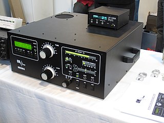
Technical specifications and detailed information on the valve audio amplifier, including its development history.
