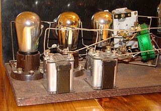
An amplifier, electronic amplifier or (informally) amp is an electronic device that can increase the magnitude of a signal. It is a two-port electronic circuit that uses electric power from a power supply to increase the amplitude of a signal applied to its input terminals, producing a proportionally greater amplitude signal at its output. The amount of amplification provided by an amplifier is measured by its gain: the ratio of output voltage, current, or power to input. An amplifier is defined as a circuit that has a power gain greater than one.

A superheterodyne receiver, often shortened to superhet, is a type of radio receiver that uses frequency mixing to convert a received signal to a fixed intermediate frequency (IF) which can be more conveniently processed than the original carrier frequency. It was invented by French radio engineer and radio manufacturer Lucien Lévy. Virtually all modern radio receivers use the superheterodyne principle.

Capacitive coupling is the transfer of energy within an electrical network or between distant networks by means of displacement current between circuit(s) nodes, induced by the electric field. This coupling can have an intentional or accidental effect.

A tuned radio frequency receiver is a type of radio receiver that is composed of one or more tuned radio frequency (RF) amplifier stages followed by a detector (demodulator) circuit to extract the audio signal and usually an audio frequency amplifier. This type of receiver was popular in the 1920s. Early examples could be tedious to operate because when tuning in a station each stage had to be individually adjusted to the station's frequency, but later models had ganged tuning, the tuning mechanisms of all stages being linked together, and operated by just one control knob. By the mid 1930s, it was replaced by the superheterodyne receiver patented by Edwin Armstrong.
A Colpitts oscillator, invented in 1918 by Canadian-American engineer Edwin H. Colpitts, is one of a number of designs for LC oscillators, electronic oscillators that use a combination of inductors (L) and capacitors (C) to produce an oscillation at a certain frequency. The distinguishing feature of the Colpitts oscillator is that the feedback for the active device is taken from a voltage divider made of two capacitors in series across the inductor.

In electronics, a center tap (CT) is a contact made to a point halfway along a winding of a transformer or inductor, or along the element of a resistor or a potentiometer.

Electronic filters are a type of signal processing filter in the form of electrical circuits. This article covers those filters consisting of lumped electronic components, as opposed to distributed-element filters. That is, using components and interconnections that, in analysis, can be considered to exist at a single point. These components can be in discrete packages or part of an integrated circuit.
In signal processing, when describing a periodic function in the time domain, the DC bias, DC component, DC offset, or DC coefficient is the mean value of the waveform. A waveform with zero mean or no DC bias is known as a DC balanced or DC free waveform.
In electronics, the Miller effect accounts for the increase in the equivalent input capacitance of an inverting voltage amplifier due to amplification of the effect of capacitance between the input and output terminals. The virtually increased input capacitance due to the Miller effect is given by

Galvanic isolation is a principle of isolating functional sections of electrical systems to prevent current flow; no direct conduction path is permitted.
In electronics, direct coupling or DC coupling is the transfer of electrical energy by means of physical contact via a conductive medium, in contrast to inductive coupling and capacitive coupling. It is a way of interconnecting two circuits such that, in addition to transferring the AC signal, the first circuit also provides DC bias to the second. Thus, DC blocking capacitors are not used or needed to interconnect the circuits. Conductive coupling passes the full spectrum of frequencies including direct current.
A direct-coupled amplifier or DC amplifier is a type of amplifier in which the output of one stage of the amplifier is coupled to the input of the next stage in such a way as to permit signals with zero frequency, also referred to as direct current, to pass from input to output. This is an application of the more general direct coupling. It was invented by Harold J Paz and Francis P. Keiper Jr. in 1955. It displaced the triode vacuum tube amplifier designed by Lee de Forest. Almost all vacuum tube circuit designs are now replaced with direct coupled transistor circuit design. It is the first transistor amplifier design that did not include coupling capacitors. The direct-coupled amplifier allowed analog circuits to be built smaller with the elimination of coupling capacitors and removed the lower frequency limitation that is dependent on capacitors.

A multistage amplifier is an electronic amplifier consisting of two or more single-stage amplifiers connected together. In this context, a single stage is an amplifier containing only a single transistor or other active device. The most common reason for using multiple stages is to increase the gain of the amplifier in applications where the input signal is very small, for instance in radio receivers. In these applications a single stage has insufficient gain by itself. In some designs it is possible to obtain more desirable values of other parameters such as input resistance and output resistance.
In the field of electronics, a technique where part of the output of a system is used at startup can be described as bootstrapping.

In electronics, biasing is the setting of DC operating conditions of an electronic component that processes time-varying signals. Many electronic devices, such as diodes, transistors and vacuum tubes, whose function is processing time-varying (AC) signals, also require a steady (DC) current or voltage at their terminals to operate correctly. This current or voltage is called bias. The AC signal applied to them is superposed on this DC bias current or voltage.

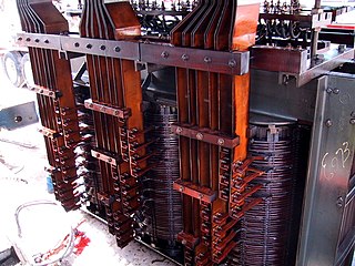
A variety of types of electrical transformer are made for different purposes. Despite their design differences, the various types employ the same basic principle as discovered in 1831 by Michael Faraday, and share several key functional parts.
Isolation amplifiers are a form of differential amplifier that allow measurement of small signals in the presence of a high common mode voltage by providing electrical isolation and an electrical safety barrier. They protect data acquisition components from common mode voltages, which are potential differences between instrument ground and signal ground. Instruments that are applied in the presence of a common mode voltage without an isolation barrier allow ground currents to circulate, leading in the best case to a noisy representation of the signal under investigation. In the worst case, assuming that the magnitude of common mode voltage or current is sufficient, instrument destruction is likely. Isolation amplifiers are used in medical instruments to ensure isolation of a patient from power supply leakage current.
Output transformerless (OTL) is a type of vacuum tube audio power amplifier, which omits an output transformer for the purpose of greater linearity and fidelity. Conventional vacuum tube amplifier designs rely upon an output transformer to couple the amplifier's output stage to the loudspeaker. Instead, OTLs use one of two primary methods for output stage coupling: direct coupling (DC) or capacitive coupling (AC).

Capacitors have many uses in electronic and electrical systems. They are so ubiquitous that it is rare that an electrical product does not include at least one for some purpose. Capacitors allow only AC signals to pass when they are charged blocking DC signals. The main components of filters are capacitors. Capacitors have the ability to connect one circuit segment to another. Capacitors are used by Dynamic Random Access Memory (DRAM) devices to represent binary information as bits.
Parasitic oscillation is an undesirable electronic oscillation in an electronic or digital device. It is often caused by feedback in an amplifying device. The problem occurs notably in RF, audio, and other electronic amplifiers as well as in digital signal processing. It is one of the fundamental issues addressed by control theory.


