Multistage amplifier

Last updated
Simplified diagram of a 2-stage cascaded amplifier Cascadeamplifier.jpg
Simplified diagram of a 2-stage cascaded amplifier

A multistage amplifier is an electronic amplifier consisting of two or more single-stage amplifiers connected together. In this context, a single stage is an amplifier containing only a single transistor (sometimes a pair of transistors) or other active device. The most common reason for using multiple stages is to increase the gain of the amplifier in applications where the input signal is very small, for instance in radio receivers. In these applications a single stage has insufficient gain by itself. In some designs it is possible to obtain more desirable values of other parameters such as input resistance and output resistance.

Contents

Connection schemes

The simplest, and most common, connection scheme is a cascade connection of identical, or similar, stages forming a cascade amplifier. [1] In a cascade connection, the output port of one stage is connected to the input port of the next. Typically, the individual stages are bipolar junction transistors (BJTs) in a common emitter configuration or field-effect transistors (FETs) in a common source configuration. There are some applications where the common base configuration is preferred. Common base has high voltage gain but no current gain. It is used in UHF television and radio receivers because its low input resistance is easier to match to antennas than common emitter. In amplifiers that have a differential input and are required to output a differential signal the stages must be differential amplifiers such as long-tailed pairs. These stages contain two transistors to deal with the differential signalling.

More complex schemes can be used with different stages having different configurations to create an amplifier whose characteristics exceed those of a single-stage for several different parameters, such as gain, input resistance and output resistance. [2] The final stage can be a common collector configuration to act as a buffer amplifier. Common collector stages have no voltage gain but high current gain and low output resistance. The load can thus draw high current without affecting the amplifier performance. A cascode connection (common emitter stage followed by common base stage) is sometimes found. Audio power amplifiers will typically have a push-pull output as the final stage.

A Darlington pair of transistors is another way of obtaining a high current gain. In this connection the emitter of the first transistor feeds the base of the second with both collectors commoned. Unlike the common collector stage, a Darlington pair can have voltage gain as well as current gain. A Darlington pair is usually treated as being a single stage rather than two separate stages. It is connected in the same way as a single transistor would be, and is often packaged as a single device.

Overall negative feedback may be applied to the amplifier. This reduces voltage gain but has several desirable effects; input resistance is increased, output resistance is decreased, and bandwidth is increased.

Overall gain

The complication in calculating the gain of cascaded stages is the non-ideal coupling between stages due to loading. Two cascaded common emitter stages are shown. Because the input resistance of the second stage forms a voltage divider with the output resistance of the first stage, the total gain is not the product of the individual (separated) stages.

The overall gain of a multistage amplifier is the product of the gains of the individual stages (ignoring potential loading effects):

Gain (A) = A1* A2*A3 *A4 *... *An.

Alternately, if the gain of each amplifier stage is expressed in decibels (dB), the total gain is the sum of the gains of the individual stages:

Gain in dB (A) = A1 + A2 + A3 + A4 + ... An

Inter-stage coupling

There are a number of choices for the method of coupling the amplifier stages together. In the direct-coupled amplifier, as the name suggests, the stages are connected by simple conductors between the output of one stage and the input of the next This is necessary where the amplifier is required to work at DC, such as in instrumentation amplifiers, but has several drawbacks. The direct connection causes the bias circuits of adjacent stages to interact with each other. This complicates the design and leads to compromises on other amplifier parameters. DC amplifiers are also subject to drift requiring careful adjustment and high stability components.

Where DC amplification is not required, a common choice is RC coupling. In this scheme a capacitor is connected in series between stage outputs and inputs. Since the capacitor will not pass DC the stage biases cannot interact. The output of the amplifier will not drift from zero when there is no input. The capacitance (C) of the capacitor and the input and output resistances of the stages form an RC circuit. This acts as a crude high-pass filter. The capacitor value must be made large enough that this filter passes the lowest frequency of interest. For audio amplifiers, this value can be relatively large, but at radio frequencies it is a small component of insignificant cost compared to the overall amplifier.

Transformer coupling is an alternative AC coupling. Like RC coupling, it isolates DC between stages. However, transformers are bulkier and much more expensive than capacitors so is used less often. Transformer coupling comes into its own in tuned amplifiers. The inductance of the transformer windings serves as the inductor of an LC tuned circuit. If both sides of the transformer are tuned it is called a double-tuned amplifier. Staggered tuning is where each stage is tuned to a different frequency in order to improve bandwidth at the expense of gain.

Optical coupling is achieved using opto-isolators between stages. These have the advantage of providing complete electrical isolation between stages so provides DC isolation and avoids interaction between stages. Optical isolation is sometimes done for electrical safety reasons. It can also be used to provide a balanced to unbalanced transition.

Related Research Articles

<span class="mw-page-title-main">Amplifier</span> Electronic device/component that increases the strength of a signal

An amplifier, electronic amplifier or (informally) amp is an electronic device that can increase the magnitude of a signal. It is a two-port electronic circuit that uses electric power from a power supply to increase the amplitude of a signal applied to its input terminals, producing a proportionally greater amplitude signal at its output. The amount of amplification provided by an amplifier is measured by its gain: the ratio of output voltage, current, or power to input. An amplifier is defined as a circuit that has a power gain greater than one.

<span class="mw-page-title-main">Operational amplifier</span> High-gain voltage amplifier with a differential input

An operational amplifier is a DC-coupled high-gain electronic voltage amplifier with a differential input and, usually, a single-ended output. In this configuration, an op amp produces an output potential that is typically 100,000 times larger than the potential difference between its input terminals. The operational amplifier traces its origin and name to analog computers, where they were used to perform mathematical operations in linear, non-linear, and frequency-dependent circuits.

In electronics, a multi-transistor configuration called the Darlington configuration is a circuit consisting of two bipolar transistors with the emitter of one transistor connected to the base of the other, such that the current amplified by the first transistor is amplified further by the second one. The collectors of both transistors are connected together. This configuration has a much higher current gain than each transistor taken separately. It acts like and is often packaged as a single transistor. It was invented in 1953 by Sidney Darlington.

<span class="mw-page-title-main">Emitter-coupled logic</span> Integrated circuit logic family

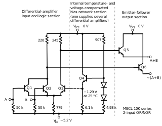
In electronics, emitter-coupled logic (ECL) is a high-speed integrated circuit bipolar transistor logic family. ECL uses an overdriven bipolar junction transistor (BJT) differential amplifier with single-ended input and limited emitter current to avoid the saturated region of operation and its slow turn-off behavior. As the current is steered between two legs of an emitter-coupled pair, ECL is sometimes called current-steering logic (CSL), current-mode logic (CML) or current-switch emitter-follower (CSEF) logic.

<span class="mw-page-title-main">Common base</span>

In electronics, a common-base amplifier is one of three basic single-stage bipolar junction transistor (BJT) amplifier topologies, typically used as a current buffer or voltage amplifier.

<span class="mw-page-title-main">Differential amplifier</span> Electrical circuit component which amplifies the difference of two analog signals

A differential amplifier is a type of electronic amplifier that amplifies the difference between two input voltages but suppresses any voltage common to the two inputs. It is an analog circuit with two inputs and and one output , in which the output is ideally proportional to the difference between the two voltages:

The Hartley oscillator is an electronic oscillator circuit in which the oscillation frequency is determined by a tuned circuit consisting of capacitors and inductors, that is, an LC oscillator. The circuit was invented in 1915 by American engineer Ralph Hartley. The distinguishing feature of the Hartley oscillator is that the tuned circuit consists of a single capacitor in parallel with two inductors in series, and the feedback signal needed for oscillation is taken from the center connection of the two inductors.

<span class="mw-page-title-main">Buffer amplifier</span> Electronic amplifier, a circuit component

In electronics, a buffer amplifier is a unity gain amplifier that copies a signal from one circuit to another while transforming its electrical impedance to provide a more ideal source. This "buffers" the signal source in the first circuit against being affected by currents from the electrical load of the second circuit and may simply be called a buffer or follower when context is clear.

<span class="mw-page-title-main">Common emitter</span> Type of electronic amplifier using a bipolar junction transistor

In electronics, a common-emitter amplifier is one of three basic single-stage bipolar-junction-transistor (BJT) amplifier topologies, typically used as a voltage amplifier. It offers high current gain, medium input resistance and a high output resistance. The output of a common emitter amplifier is inverted; i.e. for a sine wave input signal, the output signal is 180 degrees out of phase with respect to the input.

<span class="mw-page-title-main">Common collector</span> Type of transistor amplifier

In electronics, a common collector amplifier is one of three basic single-stage bipolar junction transistor (BJT) amplifier topologies, typically used as a voltage buffer.

<span class="mw-page-title-main">Current source</span> Electronic component delivering stable electric current regardless of voltage

A current source is an electronic circuit that delivers or absorbs an electric current which is independent of the voltage across it.

<span class="mw-page-title-main">Push–pull output</span> Type of electronic circuit

A push–pull amplifier is a type of electronic circuit that uses a pair of active devices that alternately supply current to, or absorb current from, a connected load. This kind of amplifier can enhance both the load capacity and switching speed.

A Colpitts oscillator, invented in 1918 by Canadian-American engineer Edwin H. Colpitts using vacuum tubes, is one of a number of designs for LC oscillators, electronic oscillators that use a combination of inductors (L) and capacitors (C) to produce an oscillation at a certain frequency. The distinguishing feature of the Colpitts oscillator is that the feedback for the active device is taken from a voltage divider made of two capacitors in series across the inductor.

<span class="mw-page-title-main">Center tap</span> Contact made to a point halfway along a winding of a transformer or inductor

In electronics, a center tap (CT) is a contact made to a point halfway along a winding of a transformer or inductor, or along the element of a resistor or a potentiometer.

<span class="mw-page-title-main">Electronic component</span> Discrete device in an electronic system

An electronic component is any basic discrete electronic device or physical entity part of an electronic system used to affect electrons or their associated fields. Electronic components are mostly industrial products, available in a singular form and are not to be confused with electrical elements, which are conceptual abstractions representing idealized electronic components and elements. A datasheet for an electronic component is a technical document that provides detailed information about the component's specifications, characteristics, and performance.

The cascode is a two-stage amplifier that consists of a common-emitter stage feeding into a common-base stage.

In electronics, the Miller effect accounts for the increase in the equivalent input capacitance of an inverting voltage amplifier due to amplification of the effect of capacitance between the input and output terminals. The virtually increased input capacitance due to the Miller effect is given by

Technical specifications and detailed information on the valve audio amplifier, including its development history.

<span class="mw-page-title-main">Double-tuned amplifier</span>

A double-tuned amplifier is a tuned amplifier with transformer coupling between the amplifier stages in which the inductances of both the primary and secondary windings are tuned separately with a capacitor across each. The scheme results in a wider bandwidth and steeper skirts than a single tuned circuit would achieve.

<span class="mw-page-title-main">Diamond buffer</span>

The diamond buffer or diamond follower is a four-transistor, two-stage, push-pull, translinear emitter follower, or less commonly source follower, in which the input transistors are folded, or placed upside-down with respect to the output transistors. Like any unity buffer, the diamond buffer does not alter the phase and magnitude of input voltage signal; its primary purpose is to interface a high-impedance voltage source with a low-impedance, high-current load. Unlike the more common compound emitter follower, where each input transistor drives the output transistor of the same polarity, each input transistor of a diamond buffer drives the output transistor of the opposite polarity. When the transistors operate in close thermal contact, the input transistors stabilize the idle current of the output pair, eliminating the need for a bias spreader.

References

  1. Innovatia: amplifier circuits
  2. Jaeger, Richard C. (2015). Microelectronic circuit design. Travis N. Blalock (Fifth ed.). New York, NY. ISBN   978-0-07-352960-8. OCLC   893721562.{{cite book}}: CS1 maint: location missing publisher (link)