
An inductor, also called a coil, choke, or reactor, is a passive two-terminal electrical component that stores energy in a magnetic field when electric current flows through it. An inductor typically consists of an insulated wire wound into a coil.

A Tesla coil is an electrical resonant transformer circuit designed by inventor Nikola Tesla in 1891. It is used to produce high-voltage, low-current, high-frequency alternating-current electricity. Tesla experimented with a number of different configurations consisting of two, or sometimes three, coupled resonant electric circuits.
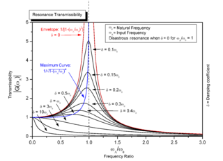
Resonance describes the phenomenon of increased amplitude that occurs when the frequency of an applied periodic force is equal or close to a natural frequency of the system on which it acts. When an oscillating force is applied at a resonant frequency of a dynamic system, the system will oscillate at a higher amplitude than when the same force is applied at other, non-resonant frequencies.

A rectifier is an electrical device that converts alternating current (AC), which periodically reverses direction, to direct current (DC), which flows in only one direction. The reverse operation is performed by an inverter.

Inductance is the tendency of an electrical conductor to oppose a change in the electric current flowing through it. The flow of electric current creates a magnetic field around the conductor. The field strength depends on the magnitude of the current, and follows any changes in current. From Faraday's law of induction, any change in magnetic field through a circuit induces an electromotive force (EMF) (voltage) in the conductors, a process known as electromagnetic induction. This induced voltage created by the changing current has the effect of opposing the change in current. This is stated by Lenz's law, and the voltage is called back EMF.

Johnson–Nyquist noise is the electronic noise generated by the thermal agitation of the charge carriers inside an electrical conductor at equilibrium, which happens regardless of any applied voltage. Thermal noise is present in all electrical circuits, and in sensitive electronic equipment can drown out weak signals, and can be the limiting factor on sensitivity of electrical measuring instruments. Thermal noise increases with temperature. Some sensitive electronic equipment such as radio telescope receivers are cooled to cryogenic temperatures to reduce thermal noise in their circuits. The generic, statistical physical derivation of this noise is called the fluctuation-dissipation theorem, where generalized impedance or generalized susceptibility is used to characterize the medium.
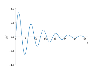
In physics and engineering, the quality factor or Q factor is a dimensionless parameter that describes how underdamped an oscillator or resonator is. It is defined as the ratio of the initial energy stored in the resonator to the energy lost in one radian of the cycle of oscillation. Q factor is alternatively defined as the ratio of a resonator's centre frequency to its bandwidth when subject to an oscillating driving force. These two definitions give numerically similar, but not identical, results. Higher Q indicates a lower rate of energy loss and the oscillations die out more slowly. A pendulum suspended from a high-quality bearing, oscillating in air, has a high Q, while a pendulum immersed in oil has a low one. Resonators with high quality factors have low damping, so that they ring or vibrate longer.
A resistor–capacitor circuit, or RC filter or RC network, is an electric circuit composed of resistors and capacitors. It may be driven by a voltage or current source and these will produce different responses. A first order RC circuit is composed of one resistor and one capacitor and is the simplest type of RC circuit.

An antenna tuner is an electronic device inserted into the feedline between a radio transmitter and its antenna. Its purpose is to optimize power transfer by matching the impedance of the radio to the impedance of the end of the feedline connecting the antenna to the transmitter.

An LC circuit, also called a resonant circuit, tank circuit, or tuned circuit, is an electric circuit consisting of an inductor, represented by the letter L, and a capacitor, represented by the letter C, connected together. The circuit can act as an electrical resonator, an electrical analogue of a tuning fork, storing energy oscillating at the circuit's resonant frequency.

In electronics, a common-source amplifier is one of three basic single-stage field-effect transistor (FET) amplifier topologies, typically used as a voltage or transconductance amplifier. The easiest way to tell if a FET is common source, common drain, or common gate is to examine where the signal enters and leaves. The remaining terminal is what is known as "common". In this example, the signal enters the gate, and exits the drain. The only terminal remaining is the source. This is a common-source FET circuit. The analogous bipolar junction transistor circuit may be viewed as a transconductance amplifier or as a voltage amplifier.. As a transconductance amplifier, the input voltage is seen as modulating the current going to the load. As a voltage amplifier, input voltage modulates the current flowing through the FET, changing the voltage across the output resistance according to Ohm's law. However, the FET device's output resistance typically is not high enough for a reasonable transconductance amplifier, nor low enough for a decent voltage amplifier. As seen below in the formula, the voltage gain depends on the load resistance, so it cannot be applied to drive low-resistance devices, such as a speaker. Another major drawback is the amplifier's limited high-frequency response. Therefore, in practice the output often is routed through either a voltage follower, or a current follower, to obtain more favorable output and frequency characteristics. The CS–CG combination is called a cascode amplifier.

The gain–bandwidth product for an amplifier is the product of the amplifier's bandwidth and the gain at which the bandwidth is measured.
In electronics, the Miller effect accounts for the increase in the equivalent input capacitance of an inverting voltage amplifier due to amplification of the effect of capacitance between the input and output terminals. The virtually increased input capacitance due to the Miller effect is given by
Ripple in electronics is the residual periodic variation of the DC voltage within a power supply which has been derived from an alternating current (AC) source. This ripple is due to incomplete suppression of the alternating waveform after rectification. Ripple voltage originates as the output of a rectifier or from generation and commutation of DC power.

A parametric oscillator is a driven harmonic oscillator in which the oscillations are driven by varying some parameter of the system at some frequency, typically different from the natural frequency of the oscillator. A simple example of a parametric oscillator is a child pumping a playground swing by periodically standing and squatting to increase the size of the swing's oscillations. The child's motions vary the moment of inertia of the swing as a pendulum. The "pump" motions of the child must be at twice the frequency of the swing's oscillations. Examples of parameters that may be varied are the oscillator's resonance frequency and damping .

Zobel networks are a type of filter section based on the image-impedance design principle. They are named after Otto Zobel of Bell Labs, who published a much-referenced paper on image filters in 1923. The distinguishing feature of Zobel networks is that the input impedance is fixed in the design independently of the transfer function. This characteristic is achieved at the expense of a much higher component count compared to other types of filter sections. The impedance would normally be specified to be constant and purely resistive. For this reason, Zobel networks are also known as constant resistance networks. However, any impedance achievable with discrete components is possible.

Resonant inductive coupling or magnetic phase synchronous coupling is a phenomenon with inductive coupling in which the coupling becomes stronger when the "secondary" (load-bearing) side of the loosely coupled coil resonates. A resonant transformer of this type is often used in analog circuitry as a bandpass filter. Resonant inductive coupling is also used in wireless power systems for portable computers, phones, and vehicles.

An RLC circuit is an electrical circuit consisting of a resistor (R), an inductor (L), and a capacitor (C), connected in series or in parallel. The name of the circuit is derived from the letters that are used to denote the constituent components of this circuit, where the sequence of the components may vary from RLC.
Staggered tuning is a technique used in the design of multi-stage tuned amplifiers whereby each stage is tuned to a slightly different frequency. In comparison to synchronous tuning it produces a wider bandwidth at the expense of reduced gain. It also produces a sharper transition from the passband to the stopband. Both staggered tuning and synchronous tuning circuits are easier to tune and manufacture than many other filter types.
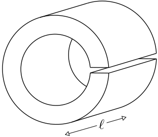
A loop-gap resonator (LGR) is an electromagnetic resonator that operates in the radio and microwave frequency ranges. The simplest LGRs are made from a conducting tube with a narrow slit cut along its length. The LGR dimensions are typically much smaller than the free-space wavelength of the electromagnetic fields at the resonant frequency. Therefore, relatively compact LGRs can be designed to operate at frequencies that are too low to be accessed using, for example, cavity resonators. These structures can have very sharp resonances making them useful for electron spin resonance (ESR) experiments, and precision measurements of electromagnetic material properties.


