Holography is a technique that enables a wavefront to be recorded and later reconstructed. It is best known as a method of generating three-dimensional images, and has a wide range of other uses, including data storage, microscopy, and interferometry. In principle, it is possible to make a hologram for any type of wave.

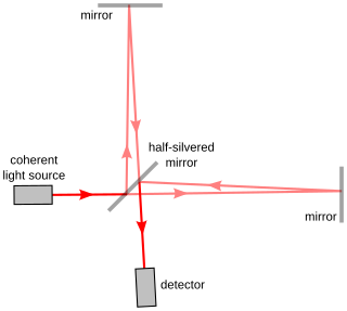
Interferometry is a technique which uses the interference of superimposed waves to extract information. Interferometry typically uses electromagnetic waves and is an important investigative technique in the fields of astronomy, fiber optics, engineering metrology, optical metrology, oceanography, seismology, spectroscopy, quantum mechanics, nuclear and particle physics, plasma physics, biomolecular interactions, surface profiling, microfluidics, mechanical stress/strain measurement, velocimetry, optometry, and making holograms.

Stereoscopy is a technique for creating or enhancing the illusion of depth in an image by means of stereopsis for binocular vision. The word stereoscopy derives from Greek στερεός (stereos) 'firm, solid' and σκοπέω (skopeō) 'to look, to see'. Any stereoscopic image is called a stereogram. Originally, stereogram referred to a pair of stereo images which could be viewed using a stereoscope.
A reference beam is a laser beam used to read and write holograms. It is one of two laser beams used to create a hologram. In order to read a hologram out, some aspects of the reference beam must be reproduced exactly as when it was used to write the hologram. As a result, usually reference beams are Gaussian beams or spherical wave beams which are fairly easy to reproduce.

A reticle, or reticule also known as a graticule, is a pattern of fine lines or markings built into the eyepiece of an optical device such as a telescopic sight, spotting scope, theodolite, optical microscope or the screen of an oscilloscope, to provide measurement references during visual inspections. Today, engraved lines or embedded fibers may be replaced by a digital image superimposed on a screen or eyepiece. Both terms may be used to describe any set of patterns used for aiding visual measurements and calibrations, but in modern use reticle is most commonly used for weapon sights, while graticule is more widely used for non-weapon measuring instruments such as oscilloscope display, astronomic telescopes, microscopes and slides, surveying instruments and other similar devices.

In ophthalmology and optometry, a slit lamp is an instrument consisting of a high-intensity light source that can be focused to shine a thin sheet of light into the eye. It is used in conjunction with a biomicroscope. The lamp facilitates an examination of the anterior segment and posterior segment of the human eye, which includes the eyelid, sclera, conjunctiva, iris, natural crystalline lens, and cornea. The binocular slit-lamp examination provides a stereoscopic magnified view of the eye structures in detail, enabling anatomical diagnoses to be made for a variety of eye conditions. A second, hand-held lens is used to examine the retina.
Holographic interferometry (HI) is a technique which enables the measurements of static and dynamic displacements of objects with optically rough surfaces at optical interferometric precision. These measurements can be applied to stress, strain and vibration analysis, as well as to non-destructive testing and radiation dosimetry. It can also be used to detect optical path length variations in transparent media, which enables, for example, fluid flow to be visualised and analyzed. It can also be used to generate contours representing the form of the surface.

Yuri Nikolayevich Denisyuk was a Russian physicist and one of the founders of optical holography in the former Soviet Union. He is known for his great contribution to holography, in particular for the so-called "Denisyuk hologram". He was a full member of the Russian Academy of Sciences, doctor of physical and mathematical sciences, professor (1980).
Digital holography is the acquisition and processing of holograms with a digital sensor array, typically a CCD camera or a similar device. Image rendering, or reconstruction of object data is performed numerically from digitized interferograms. Digital holography offers a means of measuring optical phase data and typically delivers three-dimensional surface or optical thickness images. Several recording and processing schemes have been developed to assess optical wave characteristics such as amplitude, phase, and polarization state, which make digital holography a very powerful method for metrology applications .
Computer-generated holography (CGH) is a technique that uses computer algorithms to generate holograms. It involves generating holographic interference patterns. A computer-generated hologram can be displayed on a dynamic holographic display, or it can be printed onto a mask or film using lithography. When a hologram is printed onto a mask or film, it is then illuminated by a coherent light source to display the holographic images.

Stephen Anthony Benton was the inventor of the rainbow hologram and a pioneer in medical imaging and fine arts holography. Benton held 14 patents in optical physics and photography, and taught media arts and sciences at Massachusetts Institute of Technology (MIT). He was the E. Rudge ('48) and Nancy Allen Professor of Media & Sciences, and the Director for Center for Advanced Visual Studies (CAVS) at MIT.
A holographic display is a type of 3D display that utilizes light diffraction to display a three-dimensional image to the viewer. Holographic displays are distinguished from other forms of 3D displays in that they do not require the viewer to wear any special glasses or use external equipment to be able to see the image, and do not cause a vergence-accommodation conflict.

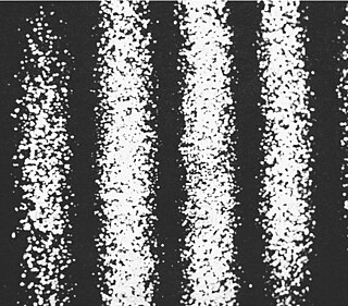
Electronic speckle pattern interferometry (ESPI), also known as TV holography, is a technique that uses laser light, together with video detection, recording and processing, to visualise static and dynamic displacements of components with optically rough surfaces. The visualisation is in the form of fringes on the image, where each fringe normally represents a displacement of half a wavelength of the light used.

A reflector sight or reflex sight is an optical sight that allows the user to look through a partially reflecting glass element and see an illuminated projection of an aiming point or some other image superimposed on the field of view. These sights work on the simple optical principle that anything at the focus of a lens or curved mirror will appear to be sitting in front of the viewer at infinity. Reflector sights employ some form of "reflector" to allow the viewer to see the infinity image and the field of view at the same time, either by bouncing the image created by lens off a slanted glass plate, or by using a mostly clear curved glass reflector that images the reticle while the viewer looks through the reflector. Since the reticle is at infinity, it stays in alignment with the device to which the sight is attached regardless of the viewer's eye position, removing most of the parallax and other sighting errors found in simple sighting devices.

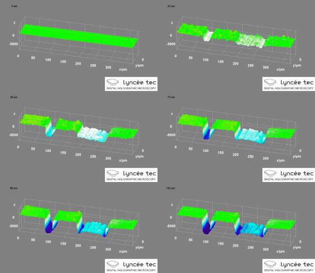
Digital holographic microscopy (DHM) is digital holography applied to microscopy. Digital holographic microscopy distinguishes itself from other microscopy methods by not recording the projected image of the object. Instead, the light wave front information originating from the object is digitally recorded as a hologram, from which a computer calculates the object image by using a numerical reconstruction algorithm. The image forming lens in traditional microscopy is thus replaced by a computer algorithm. Other closely related microscopy methods to digital holographic microscopy are interferometric microscopy, optical coherence tomography and diffraction phase microscopy. Common to all methods is the use of a reference wave front to obtain amplitude (intensity) and phase information. The information is recorded on a digital image sensor or by a photodetector from which an image of the object is created (reconstructed) by a computer. In traditional microscopy, which do not use a reference wave front, only intensity information is recorded and essential information about the object is lost.
Specular holography is a technique for making three dimensional imagery by controlling the motion of specular glints on a two-dimensional surface. The image is made of many specularities and has the appearance of a 3D surface-stippling made of dots of light. Unlike conventional wavefront holograms, specular holograms do not depend on wave optics, photographic media, or lasers.

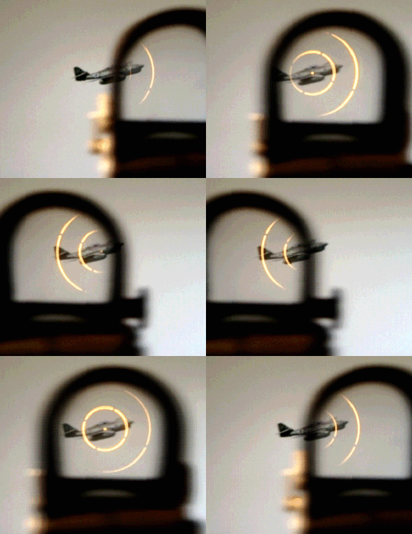
A holographic weapon sight or holographic diffraction sight is a non-magnifying gunsight that allows the user to look through a glass optical window and see a holographic reticle image superimposed at a distance on the field of view. The hologram of the reticle is built into the window and is illuminated by a laser diode.
A 3D display is multiscopic if it projects more than two images out into the world, unlike conventional 3D stereoscopy, which simulates a 3D scene by displaying only two different views of it, each visible to only one of the viewer's eyes. Multiscopic displays can represent the subject as viewed from a series of locations, and allow each image to be visible only from a range of eye locations narrower than the average human interocular distance of 63 mm. As a result, not only does each eye see a different image, but different pairs of images are seen from different viewing locations.
Optical holography is a technique which enables an optical wavefront to be recorded and later re-constructed. Holography is best known as a method of generating three-dimensional images but it also has a wide range of other applications.
Holography Art is a genre of artistic expression that leverages the scientific principles of holography, first conceptualized by physicist Dennis Gabor in 1947.


