Systems engineering is an interdisciplinary field of engineering and engineering management that focuses on how to design and manage complex systems over their life cycles. At its core, systems engineering utilizes systems thinking principles to organize this body of knowledge. The individual outcome of such efforts, an engineered system, can be defined as a combination of components that work in synergy to collectively perform a useful function.
In software and systems engineering, a use case is a list of actions or event steps typically defining the interactions between a role and a system to achieve a goal. The actor can be a human or other external system. In systems engineering, use cases are used at a higher level than within software engineering, often representing missions or stakeholder goals. The detailed requirements may then be captured in the Systems Modeling Language (SysML) or as contractual statements.

Object Process Methodology (OPM) is a conceptual modeling language and methodology for capturing knowledge and designing systems, specified as ISO/PAS 19450. Based on a minimal universal ontology of stateful objects and processes that transform them, OPM can be used to formally specify the function, structure, and behavior of artificial and natural systems in a large variety of domains.

In software engineering, a class diagram in the Unified Modeling Language (UML) is a type of static structure diagram that describes the structure of a system by showing the system's classes, their attributes, operations, and the relationships among objects.
This glossary of Unified Modeling Language terms covers all versions of UML. Individual entries will point out any distinctions that exist between versions.
WebML is a visual notation and a methodology for designing complex data-intensive Web applications. It provides graphical, yet formal, specifications, embodied in a complete design process, which can be assisted by visual design tools.
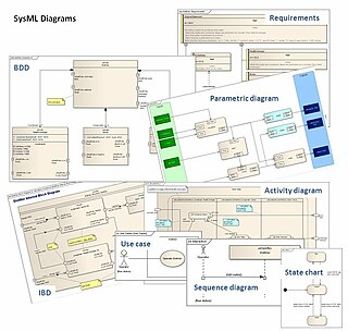
The Systems Modeling Language (SysML) is a general-purpose modeling language for systems engineering applications. It supports the specification, analysis, design, verification and validation of a broad range of systems and systems-of-systems.
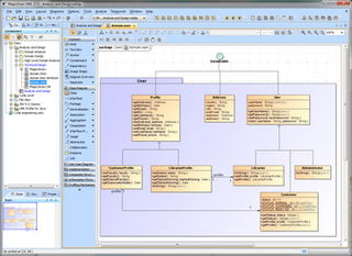
MagicDraw is a visual UML, SysML, BPMN, and UPDM modeling tool with team collaboration support. Designed for business analysts, software analysts, programmers, and QA engineers, this dynamic and versatile development tool facilitates analysis and design of object oriented (OO) systems and databases. It provides the code engineering mechanism, as well as database schema modeling, DDL generation and reverse engineering facilities.
ICONIX is a software development methodology which predates both the Rational Unified Process (RUP), Extreme Programming (XP) and Agile software development. Like RUP, the ICONIX process is UML Use Case driven but more lightweight than RUP. ICONIX provides more requirement and design documentation than XP, and aims to avoid analysis paralysis. The ICONIX Process uses only four UML based diagrams in a four-step process that turns use case text into working code.

Visual Paradigm (VP-UML) is a UML CASE Tool supporting UML 2, SysML and Business Process Modeling Notation (BPMN) from the Object Management Group (OMG). In addition to modeling support, it provides report generation and code engineering capabilities including code generation. It can reverse engineer diagrams from code, and provide round-trip engineering for various programming languages.
Requirements traceability is a sub-discipline of requirements management within software development and systems engineering. Traceability as a general term is defined by the IEEE Systems and Software Engineering Vocabulary as (1) the degree to which a relationship can be established between two or more products of the development process, especially products having a predecessor-successor or master-subordinate relationship to one another; (2) the identification and documentation of derivation paths (upward) and allocation or flowdown paths (downward) of work products in the work product hierarchy; (3) the degree to which each element in a software development product establishes its reason for existing; and (4) discernible association among two or more logical entities, such as requirements, system elements, verifications, or tasks.

In software development, the V-model represents a development process that may be considered an extension of the waterfall model, and is an example of the more general V-model. Instead of moving down in a linear way, the process steps are bent upwards after the coding phase, to form the typical V shape. The V-Model demonstrates the relationships between each phase of the development life cycle and its associated phase of testing. The horizontal and vertical axes represents time or project completeness (left-to-right) and level of abstraction, respectively.
Axiomatic Product Development Lifecycle (APDL) is a systems engineering product development model proposed by Bulent Gumus that extends the Axiomatic design (AD) method. APDL covers the whole product lifecycle including early factors that affect the entire cycle such as development testing, input constraints and system components.
EAST-ADL is an Architecture Description Language (ADL) for automotive embedded systems, developed in several European research projects. It is designed to complement AUTOSAR with descriptions at higher level of abstractions. Aspects covered by EAST-ADL include vehicle features, functions, requirements, variability, software components, hardware components and communication. Currently, it is maintained by the EAST-ADL Association in cooperation with the European FP7 MAENAD project.
A goal model is an element of requirements engineering that may also be used more widely in business analysis. Related elements include stakeholder analysis, context analysis, and scenarios, among other business and technical areas.
Software requirements is a field within software engineering that deals with establishing the needs of stakeholders that are to be solved by software. The IEEE Standard Glossary of Software Engineering Terminology defines a requirement as:
- A condition or capability needed by a user to solve a problem or achieve an objective.
- A condition or capability that must be met or possessed by a system or system component to satisfy a contract, standard, specification, or other formally imposed document.
- A documented representation of a condition or capability as in 1 or 2.

A use case diagram at its simplest is a representation of a user's interaction with the system that shows the relationship between the user and the different use cases in which the user is involved. A use case diagram can identify the different types of users of a system and the different use cases and will often be accompanied by other types of diagrams as well. The use cases are represented by either circles or ellipses.
The Lifecycle Modeling Language (LML) is an open-standard modeling language designed for systems engineering. It supports the full lifecycle: conceptual, utilization, support and retirement stages. Along with the integration of all lifecycle disciplines including, program management, systems and design engineering, verification and validation, deployment and maintenance into one framework. LML was originally designed by the LML steering committee. The specification was published October 17, 2013.

Sparx Systems Enterprise Architect is a visual modeling and design tool based on the OMG UML. The platform supports: the design and construction of software systems; modeling business processes; and modeling industry based domains. It is used by businesses and organizations to not only model the architecture of their systems, but to process the implementation of these models across the full application development life-cycle.

Capella is an open-source solution for model-based systems engineering (MBSE). Hosted at polarsys.org, this solution provides a process and tooling for graphical modeling of systems, hardware or software architectures, in accordance with the principles and recommendations defined by the Arcadia method. Capella is an initiative of PolarSys, one of several Eclipse Foundation working groups.