Related Research Articles

In telecommunications, a collinear antenna array is an array of dipole or quarter-wave antennas mounted in such a manner that the corresponding elements of each antenna are parallel and collinear; that is, they are located along a common axis.

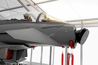
In antenna theory, a phased array usually means an electronically scanned array, a computer-controlled array of antennas which creates a beam of radio waves that can be electronically steered to point in different directions without moving the antennas.

In telecommunications and radar, a reflective array antenna is a class of directive antennas in which multiple driven elements are mounted in front of a flat surface designed to reflect the radio waves in a desired direction. They are a type of array antenna. They are often used in the VHF and UHF frequency bands. VHF examples are generally large and resemble a highway billboard, so they are sometimes called billboard antennas. Other names are bedspring array and bowtie array depending on the type of elements making up the antenna. The curtain array is a larger version used by shortwave radio broadcasting stations.

In radio engineering, an antenna or aerial is the interface between radio waves propagating through space and electric currents moving in metal conductors, used with a transmitter or receiver. In transmission, a radio transmitter supplies an electric current to the antenna's terminals, and the antenna radiates the energy from the current as electromagnetic waves. In reception, an antenna intercepts some of the power of a radio wave in order to produce an electric current at its terminals, that is applied to a receiver to be amplified. Antennas are essential components of all radio equipment.

A Yagi–Uda antenna, or simply Yagi antenna, is a directional antenna consisting of two or more parallel resonant antenna elements in an end-fire array; these elements are most often metal rods acting as half-wave dipoles. Yagi–Uda antennas consist of a single driven element connected to a radio transmitter and/or receiver through a transmission line, and additional "passive radiators" with no electrical connection, usually including one so-called reflector and any number of directors. It was invented in 1926 by Shintaro Uda of Tohoku Imperial University, Japan, with a lesser role played by his boss Hidetsugu Yagi.

A directional antenna or beam antenna is an antenna which radiates or receives greater radio wave power in specific directions. Directional antennas can radiate radio waves in beams, when greater concentration of radiation in a certain direction is desired, or in receiving antennas receive radio waves from one specific direction only. This can increase the power transmitted to receivers in that direction, or reduce interference from unwanted sources. This contrasts with omnidirectional antennas such as dipole antennas which radiate radio waves over a wide angle, or receive from a wide angle.

Direction finding (DF), or radio direction finding (RDF), is – in accordance with International Telecommunication Union (ITU) – defined as radio location that uses the reception of radio waves to determine the direction in which a radio station or an object is located. This can refer to radio or other forms of wireless communication, including radar signals detection and monitoring (ELINT/ESM). By combining the direction information from two or more suitably spaced receivers, the source of a transmission may be located via triangulation. Radio direction finding is used in the navigation of ships and aircraft, to locate emergency transmitters for search and rescue, for tracking wildlife, and to locate illegal or interfering transmitters. RDF was important in combating German threats during both the World War II Battle of Britain and the long running Battle of the Atlantic. In the former, the Air Ministry also used RDF to locate its own fighter groups and vector them to detected German raids.

An active electronically scanned array (AESA) is a type of phased array antenna, which is a computer-controlled array antenna in which the beam of radio waves can be electronically steered to point in different directions without moving the antenna. In the AESA, each antenna element is connected to a small solid-state transmit/receive module (TRM) under the control of a computer, which performs the functions of a transmitter and/or receiver for the antenna. This contrasts with a passive electronically scanned array (PESA), in which all the antenna elements are connected to a single transmitter and/or receiver through phase shifters under the control of the computer. AESA's main use is in radar, and these are known as active phased array radar (APAR).
Beamforming or spatial filtering is a signal processing technique used in sensor arrays for directional signal transmission or reception. This is achieved by combining elements in an antenna array in such a way that signals at particular angles experience constructive interference while others experience destructive interference. Beamforming can be used at both the transmitting and receiving ends in order to achieve spatial selectivity. The improvement compared with omnidirectional reception/transmission is known as the directivity of the array.

Antenna diversity, also known as space diversity or spatial diversity, is any one of several wireless diversity schemes that uses two or more antennas to improve the quality and reliability of a wireless link. Often, especially in urban and indoor environments, there is no clear line-of-sight (LOS) between transmitter and receiver. Instead the signal is reflected along multiple paths before finally being received. Each of these bounces can introduce phase shifts, time delays, attenuations, and distortions that can destructively interfere with one another at the aperture of the receiving antenna.

A passive electronically scanned array (PESA), also known as passive phased array, is an antenna in which the beam of radio waves can be electronically steered to point in different directions, in which all the antenna elements are connected to a single transmitter and/or receiver. The largest use of phased arrays is in radars. Most phased array radars in the world are PESA. The civilian microwave landing system uses PESA transmit-only arrays.
Photomixing is the generation of continuous wave terahertz radiation from two lasers. The beams are mixed together and focused onto a photomixer device which generates the terahertz radiation. It is technologically significant because there are few sources capable of providing radiation in this waveband, others include frequency multiplied electronic/microwave sources, quantum cascade laser and ultrashort pulsed lasers with photoconductive switches as used in terahertz time-domain spectroscopy. The advantages of this technique are that it is continuously tunable over the frequency range from 300 GHz to 3 THz, and spectral resolutions in the order of 1 MHz can be achieved. However, the achievable power is on the order of 10−8 W.
Phased-array optics is the technology of controlling the phase and amplitude of light waves transmitting, reflecting, or captured (received) by a two-dimensional surface using adjustable surface elements. An optical phased array (OPA) is the optical analog of a radio-wave phased array. By dynamically controlling the optical properties of a surface on a microscopic scale, it is possible to steer the direction of light beams, or the view direction of sensors, without any moving parts. Phased-array beam steering is used for optical switching and multiplexing in optoelectronic devices and for aiming laser beams on a macroscopic scale.

A turnstile antenna, or crossed-dipole antenna, is a radio antenna consisting of a set of two identical dipole antennas mounted at right angles to each other and fed in phase quadrature; the two currents applied to the dipoles are 90° out of phase. The name reflects the notion the antenna looks like a turnstile when mounted horizontally. The antenna can be used in two possible modes. In normal mode the antenna radiates horizontally polarized radio waves perpendicular to its axis. In axial mode the antenna radiates circularly polarized radiation along its axis.

Metamaterial antennas are a class of antennas which use metamaterials to increase performance of miniaturized antenna systems. Their purpose, as with any electromagnetic antenna, is to launch energy into free space. However, this class of antenna incorporates metamaterials, which are materials engineered with novel, often microscopic, structures to produce unusual physical properties. Antenna designs incorporating metamaterials can step-up the antenna's radiated power.

A plasma antenna is a type of radio antenna currently in development in which plasma is used instead of the metal elements of a traditional antenna. A plasma antenna can be used for both transmission and reception. Although plasma antennas have only become practical in recent years, the idea is not new; a patent for an antenna using the concept was granted to J. Hettinger in 1919.

A batwing or super turnstile antenna is a broadcasting antenna used at VHF and UHF frequencies, named for its distinctive shape resembling a bat wing or bow tie. Stacked arrays of batwing antennas are used as television broadcasting antennas due to their omnidirectional characteristics. Batwing antennas generate a horizontally polarized signal. The advantage of the "batwing" design for television broadcasting is that it has a wide bandwidth. It was the first widely used television broadcasting antenna.

An antenna array is a set of multiple connected antennas which work together as a single antenna, to transmit or receive radio waves. The individual antennas are usually connected to a single receiver or transmitter by feedlines that feed the power to the elements in a specific phase relationship. The radio waves radiated by each individual antenna combine and superpose, adding together to enhance the power radiated in desired directions, and cancelling to reduce the power radiated in other directions. Similarly, when used for receiving, the separate radio frequency currents from the individual antennas combine in the receiver with the correct phase relationship to enhance signals received from the desired directions and cancel signals from undesired directions. More sophisticated array antennas may have multiple transmitter or receiver modules, each connected to a separate antenna element or group of elements.

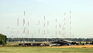
Curtain arrays are a class of large multielement directional radio transmitting wire antennas, used in the shortwave radio bands. They are a type of reflective array antenna, consisting of multiple wire dipole antennas, suspended in a vertical plane, often in front of a "curtain" reflector made of a flat vertical screen of many long parallel wires. These are suspended by support wires strung between pairs of tall steel towers, up to 90 m high. They are used for long-distance skywave transmission; they transmit a beam of radio waves at a shallow angle into the sky just above the horizon, which is reflected by the ionosphere back to Earth beyond the horizon. Curtain antennas are mostly used by international short wave radio stations to broadcast to large areas at transcontinental distances.
In radio systems, many different antenna types are used whose properties are especially crafted for particular applications. Antennas can be classified in various ways. The list below groups together antennas under common operating principles, following the way antennas are classified in many engineering textbooks.
References
- Angelo Umali's "Retrodirective Noise Correlating Radar"