Ring oiler

Last updated
Section through a bearing, showing the oil sump beneath (green) and the ring oiler (orange) in place around the shaft Bearing with ring oiler, coloured (Electrical Machinery, 1917).jpg
Section through a bearing, showing the oil sump beneath (green) and the ring oiler (orange) in place around the shaft
Section though a long Babbitt metal sleeve bearing, with two ring oilers fitted through grooves in the upper part of the bearing. Bearing with ring oiler, longitudinal section (Electrical Machinery, 1917).jpg
Section though a long Babbitt metal sleeve bearing, with two ring oilers fitted through grooves in the upper part of the bearing.

A ring oiler or oil ring is a form of oil-lubrication system for bearings.

Lubrication process or technique employed to reduce friction between, and wear of one or both, surfaces in proximity and moving relative to each other, by interposing a substance called a lubricant in between them

Lubrication is the process or technique of using a lubricant to reduce friction and/or wear in a contact between two surfaces. The study of lubrication is a discipline in the field of tribology.

Bearing (mechanical) machine element that constrains relative motion to only the desired motion, and reduces friction between moving parts

A bearing is a machine element that constrains relative motion to only the desired motion, and reduces friction between moving parts. The design of the bearing may, for example, provide for free linear movement of the moving part or for free rotation around a fixed axis; or, it may prevent a motion by controlling the vectors of normal forces that bear on the moving parts. Most bearings facilitate the desired motion by minimizing friction. Bearings are classified broadly according to the type of operation, the motions allowed, or to the directions of the loads (forces) applied to the parts.

Ring oilers were used for medium-speed applications with moderate loads, during the first half of the 20th century. These represented the later years of the stationary steam engine, and the beginnings of the high-speed steam engine, the internal combustion oil engine [1] and electrical generating equipment. [2] Before this time plain bearings were lubricated by drip-feed oil cups or manually by an engine tender with an oil can. As speeds or bearing loads later increased, forced pressure lubrication became more prevalent and the ring oiler fell from use.

Stationary steam engine

Stationary steam engines are fixed steam engines used for pumping or driving mills and factories, and for power generation. They are distinct from locomotive engines used on railways, traction engines for heavy steam haulage on roads, steam cars, agricultural engines used for ploughing or threshing, marine engines, and the steam turbines used as the mechanism of power generation for most nuclear power plants.

High-speed steam engine

High-speed steam engines were one of the final developments of the stationary steam engine. They ran at a high speed, of several hundred rpm, which was needed by tasks such as electricity generation.

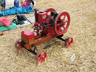
The crude oil engine is a type of internal combustion engine similar to the hot bulb engine. A crude oil engine could be driven by all sorts of oils such as engine waste oil and vegetable oils. Even peanut oil and butter could be used as fuel if necessary. Like hot bulb engines, crude oil engines were mostly used as stationary engines or in boats/ships. They can run for a very long time; for instance, at the world fair in Milan in 1906, a FRAM engine was started and ran until the exhibition was over one month later. A crude oil engine is a low RPM engine dimensioned for constant running and can last for a very long time if maintained properly. It was later replaced by the diesel engine.

A ring oiler is a simple device, consisting of a large metal ring placed around a horizontal shaft, adjacent to a bearing. An oil sump is underneath this shaft and the ring is large enough to dip into the oil. As the shaft rotates, the ring is carried round with it. The rotating ring in turn picks up some oil and deposits it onto the shaft, from where it flows sideways and lubricates the bearings. The oil ring is effectively a simple lubrication pump, with only one moving part and no complex or high-precision components. The device is crude, but automatic, effective and reliable. Unlike a drip oiler, there is also no need to close off the oiler or remove oil wicks when the machine is stopped.

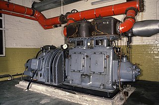
Ring oilers were used for speeds up to around 1,000 rpm. [1] Above this, the oil tended to be thrown centrifugally from the ring, rather than carried by it (although it is still currently applied on steam turbines with speeds around 3200 rpm[ citation needed ]). The bearing must also remain horizontal and stable, so although suitable for crankshaft main bearings, they could not be used on connecting rod big end bearings. They were not used on vehicles for similar reasons, although the engines concerned at this time were anyway too large and heavy for practical mobile use. Automatic ring oilers were particularly useful for large engines with multiple horizontally opposed cylinders, where it was otherwise difficult to access the central main bearings. [1] Ring oilers were most suited where bearing side-loads were relatively light, but the bearing capacity required more lubrication than could be supplied by a drip feed oiler. For this reason they were widely used on larger electric motors and generators. [2] [3]

Connecting rod mechanical element that connect the piston to the crank or crankshaft.

A connecting rod is a rigid member which connects a piston to a crank or crankshaft in a reciprocating engine. Together with the crank, it forms a simple mechanism that converts reciprocating motion into rotating motion.

Related Research Articles

Ball bearing type of rolling-element bearing that uses balls to maintain the separation between the bearing races.The purpose of a ball bearing is to reduce rotational friction and support radial and axial loads

A ball bearing is a type of rolling-element bearing that uses balls to maintain the separation between the bearing races.

Fluid bearings are bearings in which the load is supported by a thin layer of rapidly moving pressurized liquid or gas between the bearing surfaces. Since there is no contact between the moving parts, there is no sliding friction, allowing fluid bearings to have lower friction, wear and vibration than many other types of bearings.

Transmission (mechanics) machine in a power transmission system for controlled application of the power;gearbox,uses gears/gear trains to provide speed,torque conversions from a rotating power source to another device;reduces the higher engine speed to the slower wheel speed

A transmission is a machine in a power transmission system, which provides controlled application of the power. Often the term transmission refers simply to the gearbox that uses gears and gear trains to provide speed and torque conversions from a rotating power source to another device.

Manual transmission type of transmission used in motor vehicle applications

A manual transmission, also known as a manual gearbox, a standard transmission or colloquially in some countries as a stick shift, is a type of transmission used in motor vehicle applications. It uses a driver-operated clutch, usually engaged and disengaged by a foot pedal or hand lever, for regulating torque transfer from the engine to the transmission; and a gear selector that can be operated by hand or foot.

Plain bearing simplest type of bearing, comprising just a bearing surface and no rolling elements

A plain bearing, or more commonly sliding bearing and slide bearing, is the simplest type of bearing, comprising just a bearing surface and no rolling elements. Therefore, the journal slides over the bearing surface. The simplest example of a plain bearing is a shaft rotating in a hole. A simple linear bearing can be a pair of flat surfaces designed to allow motion; e.g., a drawer and the slides it rests on or the ways on the bed of a lathe.

Babbitt (alloy) alloys used for the bearing surface in a plain bearing

Babbitt, also called Babbitt metal or bearing metal, is any of several alloys used for the bearing surface in a plain bearing.

Line shaft power driven rotating shaft for power transmission

A line shaft is a power driven rotating shaft for power transmission that was used extensively from the Industrial Revolution until the early 20th century. Prior to the widespread use of electric motors small enough to be connected directly to each piece of machinery, line shafting was used to distribute power from a large central power source to machinery throughout a workshop or an industrial complex. The central power source could be a water wheel, turbine, windmill, animal power or a steam engine. Power was distributed from the shaft to the machinery by a system of belts, pulleys and gears known as millwork.

Condition monitoring is the process of monitoring a parameter of condition in machinery, in order to identify a significant change which is indicative of a developing fault. It is a major component of predictive maintenance. The use of condition monitoring allows maintenance to be scheduled, or other actions to be taken to prevent consequential damages and avoid its consequences. Condition monitoring has a unique benefit in that conditions that would shorten normal lifespan can be addressed before they develop into a major failure. Condition monitoring techniques are normally used on rotating equipment, auxiliary systems and other machinery, while periodic inspection using non-destructive testing (NDT) techniques and fit for service (FFS) evaluation are used for static plant equipment such as steam boilers, piping and heat exchangers.

Tapered roller bearing

Tapered roller bearings are rolling element bearings that can support axial forces as well as radial forces.

Constant-speed propeller

A constant-speed propeller is a variable-pitch aircraft propeller that automatically changes its blade pitch in order to maintain a chosen rotational speed. The power delivered is proportional to the arithmetic product of rotational speed and torque, and the propeller operation places emphasis on torque. The operation better suits modern engines, particularly supercharged and gas turbine types.

Hydraulic motor hydro pohon

A hydraulic motor is a mechanical actuator that converts hydraulic pressure and flow into torque and angular displacement (rotation). The hydraulic motor is the rotary counterpart of the hydraulic cylinder as a linear actuator. Most broadly, the category of devices called hydraulic motors has sometimes included those that run on hydropower—namely, water engines and water motors—but in today's terminology the name usually refers more specifically to motors that use hydraulic fluid as part of closed hydraulic circuits in modern hydraulic machinery.

Hit-and-miss engine

A hit-and-miss engine is a type of four-stroke internal combustion engine that is controlled by a governor to operate at a set speed. It was conceived in the late 19th century and produced by various companies from the 1890s through approximately the 1940s. The name comes from the speed control on these engines: they fire ("hit") only when operating at or below a set speed, and cycle without firing ("miss") when they exceed their set speed. This is as compared to the "throttle governed" method of speed control. The sound made when the engine is running without a load is a distinctive "POP whoosh whoosh whoosh whoosh POP" as the engine fires and then coasts until the speed decreases and it fires again to maintain its average speed.

Oil pump (internal combustion engine) oil pumps

The oil pump in an internal combustion engine circulates engine oil under pressure to the rotating bearings, the sliding pistons and the camshaft of the engine. This lubricates the bearings, allows the use of higher-capacity fluid bearings and also assists in cooling the engine.

A thrust block, also known as a thrust box, is a specialised form of thrust bearing used in ships, to resist the thrust of the propeller shaft and transmit it to the hull.

A stave bearing is a simple journal bearing where a shaft rotates in a bearing housing. Rather than the usual arrangement where the fixed part of the bearing surrounds most of the circumference of the shaft in one or two pieces, a stave bearing uses a large number of axial staves to support the shaft. A large housing is made with grooves running along the shaft, these grooves being filled with strips of suitable material, originally wood.

Total-loss oiling system

A total-loss oiling system is an engine lubrication system whereby oil is introduced into the engine, and then either burned or ejected overboard. Now rare in four-stroke engines, total loss oiling is still used in many two-stroke engines.

Rotary union

A rotary union is a union that allows for rotation of the united parts. It is thus a device that provides a seal between a stationary supply passage and a rotating part to permit the flow of a fluid into and/or out of the rotating part. Fluids typically used with rotary joints and rotating unions include various heat transfer media and fluid power media such as steam, water, thermal oil, hydraulic fluid, and coolants. A rotary union is sometimes referred to as a rotating union, rotary valve, swivel union,rotorseal,rotary couplings, rotary joint, rotating joints, hydraulic coupling, pneumatic rotary union, through bore rotary union, air rotary union, electrical rotary union, or vacuum rotary union

Cyclone Waste Heat Engine

The Cyclone Waste Heat Engine (WHE) is a small steam engine developed to produce power from steam created from waste heat. It is an offshoot of the development of the Cyclone Mark V Engine by the company Cyclone Power Technologies of Pampano Beach, Florida. The original versions were designed by inventor Harry Schoell, founder of Cyclone Power Technologies and the later versions have been designed by the Ohio State University Center for Automotive Research (OSU-CAR).

References

  1. 1 2 3 Williams, D.S.D.; Millar Smith, J. (1939). The Oil Engine (journal), ed. The Oil Engine Manual. London: Temple Press. pp. 65–67.
  2. 1 2 Croft, Terrell (1917). Electrical Machinery. McGraw-Hill. p. 144.
  3. "Lubrication". p. 6-3.