
Radar is a detection system that uses radio waves to determine the distance (ranging), angle, and radial velocity of objects relative to the site. It can be used to detect aircraft, ships, spacecraft, guided missiles, motor vehicles, weather formations, and terrain. A radar system consists of a transmitter producing electromagnetic waves in the radio or microwaves domain, a transmitting antenna, a receiving antenna and a receiver and processor to determine properties of the objects. Radio waves from the transmitter reflect off the objects and return to the receiver, giving information about the objects' locations and speeds.

A superheterodyne receiver, often shortened to superhet, is a type of radio receiver that uses frequency mixing to convert a received signal to a fixed intermediate frequency (IF) which can be more conveniently processed than the original carrier frequency. It was long believed to have been invented by US engineer Edwin Armstrong, but after some controversy the earliest patent for the invention is now credited to French radio engineer and radio manufacturer Lucien Lévy. Virtually all modern radio receivers use the superheterodyne principle; except those software-defined radios using direct sampling.
In electronics, noise temperature is one way of expressing the level of available noise power introduced by a component or source. The power spectral density of the noise is expressed in terms of the temperature that would produce that level of Johnson–Nyquist noise, thus:

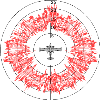
A Doppler radar is a specialized radar that uses the Doppler effect to produce velocity data about objects at a distance. It does this by bouncing a microwave signal off a desired target and analyzing how the object's motion has altered the frequency of the returned signal. This variation gives direct and highly accurate measurements of the radial component of a target's velocity relative to the radar.

Automatic gain control (AGC) is a closed-loop feedback regulating circuit in an amplifier or chain of amplifiers, the purpose of which is to maintain a suitable signal amplitude at its output, despite variation of the signal amplitude at the input. The average or peak output signal level is used to dynamically adjust the gain of the amplifiers, enabling the circuit to work satisfactorily with a greater range of input signal levels. It is used in most radio receivers to equalize the average volume (loudness) of different radio stations due to differences in received signal strength, as well as variations in a single station's radio signal due to fading. Without AGC the sound emitted from an AM radio receiver would vary to an extreme extent from a weak to a strong signal; the AGC effectively reduces the volume if the signal is strong and raises it when it is weaker. In a typical receiver the AGC feedback control signal is usually taken from the detector stage and applied to control the gain of the IF or RF amplifier stages.
A continuous wave or continuous waveform (CW) is an electromagnetic wave of constant amplitude and frequency, typically a sine wave, that for mathematical analysis is considered to be of infinite duration. It may refer to e.g. a laser or particle accelerator having a continuous output, as opposed to a pulsed output.
In signal processing and electronics, the frequency response of a system is the quantitative measure of the magnitude and phase of the output as a function of input frequency. The frequency response is widely used in the design and analysis of systems, such as audio and control systems, where they simplify mathematical analysis by converting governing differential equations into algebraic equations. In an audio system, it may be used to minimize audible distortion by designing components so that the overall response is as flat (uniform) as possible across the system's bandwidth. In control systems, such as a vehicle's cruise control, it may be used to assess system stability, often through the use of Bode plots. Systems with a specific frequency response can be designed using analog and digital filters.

In signal processing, a band-stop filter or band-rejection filter is a filter that passes most frequencies unaltered, but attenuates those in a specific range to very low levels. It is the opposite of a band-pass filter. A notch filter is a band-stop filter with a narrow stopband.
Radar cross-section (RCS), also called radar signature, is a measure of how detectable an object is by radar. A larger RCS indicates that an object is more easily detected.

Direction finding (DF), or radio direction finding (RDF), is – in accordance with International Telecommunication Union (ITU) – defined as radio location that uses the reception of radio waves to determine the direction in which a radio station or an object is located. This can refer to radio or other forms of wireless communication, including radar signals detection and monitoring (ELINT/ESM). By combining the direction information from two or more suitably spaced receivers, the source of a transmission may be located via triangulation. Radio direction finding is used in the navigation of ships and aircraft, to locate emergency transmitters for search and rescue, for tracking wildlife, and to locate illegal or interfering transmitters. RDF was important in combating German threats during both the World War II Battle of Britain and the long running Battle of the Atlantic. In the former, the Air Ministry also used RDF to locate its own fighter groups and vector them to detected German raids.

The Kolchuga passive sensor is an electronic-warfare support measures system developed in the Soviet Union and manufactured in Ukraine. Its detection range is limited by line-of-sight but may be up to 800 km (500 mi) for very high altitude, very powerful emitters. Frequently referred to as Kolchuga Radar, the system is not really a radar, but an ESM system comprising three or four receivers, deployed tens of kilometres apart, which detect and track aircraft by triangulation and multilateration of their RF emissions.
A pulse-Doppler radar is a radar system that determines the range to a target using pulse-timing techniques, and uses the Doppler effect of the returned signal to determine the target object's velocity. It combines the features of pulse radars and continuous-wave radars, which were formerly separate due to the complexity of the electronics.

Continuous-wave radar is a type of radar system where a known stable frequency continuous wave radio energy is transmitted and then received from any reflecting objects. Individual objects can be detected using the Doppler effect, which causes the received signal to have a different frequency from the transmitted signal, allowing it to be detected by filtering out the transmitted frequency.

A backward wave oscillator (BWO), also called carcinotron or backward wave tube, is a vacuum tube that is used to generate microwaves up to the terahertz range. Belonging to the traveling-wave tube family, it is an oscillator with a wide electronic tuning range.
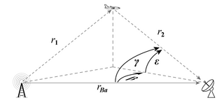
Bistatic radar is a radar system comprising a transmitter and receiver that are separated by a distance comparable to the expected target distance. Conversely, a conventional radar in which the transmitter and receiver are co-located is called a monostatic radar. A system containing multiple spatially diverse monostatic or bistatic radar components with a shared area of coverage is called multistatic radar. Many long-range air-to-air and surface-to-air missile systems use semi-active radar homing, which is a form of bistatic radar.
A radar system uses a radio-frequency electromagnetic signal reflected from a target to determine information about that target. In any radar system, the signal transmitted and received will exhibit many of the characteristics described below.

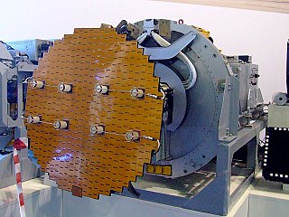
The AN/FPS-16 is a highly accurate ground-based monopulse single object tracking radar (SOTR), used extensively by the NASA manned space program, the U.S. Air Force and the U.S. Army. The accuracy of Radar Set AN/FPS-16 is such that the position data obtained from point-source targets has azimuth and elevation angular errors of less than 0.1 milliradian and range errors of less than 5 yards (5 m) with a signal-to-noise ratio of 20 decibels or greater.
Moving target indication (MTI) is a mode of operation of a radar to discriminate a target against the clutter. It describes a variety of techniques used for finding moving objects, like an aircraft, and filter out unmoving ones, like hills or trees. It contrasts with the modern stationary target indication (STI) technique, which uses details of the signal to directly determine the mechanical properties of the reflecting objects and thereby find targets whether they are moving or not.
An RF chain is a cascade of electronic components and sub-units which may include amplifiers, filters, mixers, attenuators and detectors. It can take many forms, for example, as a wide-band receiver-detector for electronic warfare (EW) applications, as a tunable narrow-band receiver for communications purposes, as a repeater in signal distribution systems, or as an amplifier and up-converters for a transmitter-driver. In this article, the term RF covers the frequency range "Medium Frequencies" up to "Microwave Frequencies", i.e. from 100 kHz to 20 GHz.

Radar angels are an effect seen on radar displays when there is a periodic structure in the view of the radar that is roughly the same length as the signal's wavelength. The angel appears to be a physically huge object on the display, often miles across, that can obscure real targets. These were first noticed in the 1940s and were a topic of considerable study in the 1950s. The underlying mechanism is due to Bragg's law.
