Related Research Articles

A logic gate is a device that performs a Boolean function, a logical operation performed on one or more binary inputs that produces a single binary output. Depending on the context, the term may refer to an ideal logic gate, one that has, for instance, zero rise time and unlimited fan-out, or it may refer to a non-ideal physical device.
Transistor–transistor logic (TTL) is a logic family built from bipolar junction transistors. Its name signifies that transistors perform both the logic function and the amplifying function, as opposed to earlier resistor–transistor logic (RTL) and diode–transistor logic (DTL).
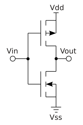
Complementary metal–oxide–semiconductor is a type of metal–oxide–semiconductor field-effect transistor (MOSFET) fabrication process that uses complementary and symmetrical pairs of p-type and n-type MOSFETs for logic functions. CMOS technology is used for constructing integrated circuit (IC) chips, including microprocessors, microcontrollers, memory chips, and other digital logic circuits. CMOS technology is also used for analog circuits such as image sensors, data converters, RF circuits, and highly integrated transceivers for many types of communication.

The 7400 series is a popular logic family of transistor–transistor logic (TTL) integrated circuits (ICs).

In electronics, a Schmitt trigger is a comparator circuit with hysteresis implemented by applying positive feedback to the noninverting input of a comparator or differential amplifier. It is an active circuit which converts an analog input signal to a digital output signal. The circuit is named a trigger because the output retains its value until the input changes sufficiently to trigger a change. In the non-inverting configuration, when the input is higher than a chosen threshold, the output is high. When the input is below a different (lower) chosen threshold the output is low, and when the input is between the two levels the output retains its value. This dual threshold action is called hysteresis and implies that the Schmitt trigger possesses memory and can act as a bistable multivibrator. There is a close relation between the two kinds of circuits: a Schmitt trigger can be converted into a latch and a latch can be converted into a Schmitt trigger.

Diode–transistor logic (DTL) is a class of digital circuits that is the direct ancestor of transistor–transistor logic. It is called so because the logic gating functions AND and OR are performed by diode logic, while logical inversion (NOT) and amplification is performed by a transistor.

In electronics and electromagnetics, slew rate is defined as the change of voltage or current, or any other electrical or electromagnetic quantity, per unit of time. Expressed in SI units, the unit of measurement is given as the change per second, but in the context of electronic circuits a slew rate is usually expressed in terms of microseconds (μs) or nanoseconds (ns).
In computer engineering, a logic family is one of two related concepts:
Propagation delay is the time duration taken for a signal to reach its destination. It can relate to networking, electronics or physics.
In digital electronics, a tri-state or three-state buffer is a type of digital buffer that has three stable states: a high output state, a low output state, and a high-impedance state. In the high-impedance state, the output of the buffer is disconnected from the output bus, allowing other devices to drive the bus without interference from the tri-state buffer. This can be useful in situations where multiple devices are connected to the same bus and need to take turns accessing it. Systems implementing three-state logic on their bus are known as a three-state bus or tri-state bus.
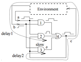
In digital computing, the Muller C-element is a small binary logic circuit widely used in design of asynchronous circuits and systems. It outputs 0 when all inputs are 0, it outputs 1 when all inputs are 1, and it retains its output state otherwise. It was specified formally in 1955 by David E. Muller and first used in ILLIAC II computer. In terms of the theory of lattices, the C-element is a semimodular distributive circuit, whose operation in time is described by a Hasse diagram. The C-element is closely related to the rendezvous and join elements, where an input is not allowed to change twice in succession. In some cases, when relations between delays are known, the C-element can be realized as a sum-of-product (SOP) circuit. Earlier techniques for implementing the C-element include Schmitt trigger, Eccles-Jordan flip-flop and last moving point flip-flop.
Power optimization is the use of electronic design automation tools to optimize (reduce) the power consumption of a digital design, such as that of an integrated circuit, while preserving the functionality.
In integrated circuit design, dynamic logic is a design methodology in combinational logic circuits, particularly those implemented in metal–oxide–semiconductor (MOS) technology. It is distinguished from the so-called static logic by exploiting temporary storage of information in stray and gate capacitances. It was popular in the 1970s and has seen a recent resurgence in the design of high-speed digital electronics, particularly central processing units (CPUs). Dynamic logic circuits are usually faster than static counterparts and require less surface area, but are more difficult to design. Dynamic logic has a higher average rate of voltage transitions than static logic, but the capacitive loads being transitioned are smaller so the overall power consumption of dynamic logic may be higher or lower depending on various tradeoffs. When referring to a particular logic family, the dynamic adjective usually suffices to distinguish the design methodology, e.g. dynamic CMOS or dynamic SOI design.
A Wilson current mirror is a three-terminal circuit that accepts an input current at the input terminal and provides a "mirrored" current source or sink output at the output terminal. The mirrored current is a precise copy of the input current. It may be used as a Wilson current source by applying a constant bias current to the input branch as in Fig. 2. The circuit is named after George R. Wilson, an integrated circuit design engineer who worked for Tektronix. Wilson devised this configuration in 1967 when he and Barrie Gilbert challenged each other to find an improved current mirror overnight that would use only three transistors. Wilson won the challenge.

A logic probe is a low-cost hand-held test probe used for analyzing and troubleshooting the logical states of a digital circuit. When many signals need to be observed or recorded simultaneously, a logic analyzer is used instead.
In electrical engineering, noise margin is the maximum voltage amplitude of extraneous signal that can be algebraically added to the noise-free worst-case input level without causing the output voltage to deviate from the allowable logic voltage level. It is commonly used in at least two contexts as follows:
Four-phase logic is a type of, and design methodology for dynamic logic. It enabled non-specialist engineers to design quite complex ICs, using either PMOS or NMOS processes. It uses a kind of 4-phase clock signal.
In electronics, pass transistor logic (PTL) describes several logic families used in the design of integrated circuits. It reduces the count of transistors used to make different logic gates, by eliminating redundant transistors. Transistors are used as switches to pass logic levels between nodes of a circuit, instead of as switches connected directly to supply voltages. This reduces the number of active devices, but has the disadvantage that the difference of the voltage between high and low logic levels decreases at each stage. Each transistor in series is less saturated at its output than at its input. If several devices are chained in series in a logic path, a conventionally constructed gate may be required to restore the signal voltage to the full value. By contrast, conventional CMOS logic switches transistors so the output connects to one of the power supply rails, so logic voltage levels in a sequential chain do not decrease. Simulation of circuits may be required to ensure adequate performance.

In electronics, flip-flops and latches are circuits that have two stable states that can store state information – a bistable multivibrator. The circuit can be made to change state by signals applied to one or more control inputs and will output its state. It is the basic storage element in sequential logic. Flip-flops and latches are fundamental building blocks of digital electronics systems used in computers, communications, and many other types of systems.

The memory cell is the fundamental building block of computer memory. The memory cell is an electronic circuit that stores one bit of binary information and it must be set to store a logic 1 and reset to store a logic 0. Its value is maintained/stored until it is changed by the set/reset process. The value in the memory cell can be accessed by reading it.
References
- ↑ The Integrated Circuit Data Book. Motorola Semiconductor Products, Inc. 1968. pp. 2.81–2.84.
- ↑ Stephen A. Ward and Robert H. Halstead (1990). Computation Structures. MIT Press. pp. 5–7. ISBN 9780262231398.