
In electrical engineering, ground or earth is the reference point in an electrical circuit from which voltages are measured, a common return path for electric current, or a direct physical connection to the earth.
In electric and electronic systems, reactance is the opposition of a circuit element to the flow of current due to that element's inductance or capacitance. Greater reactance leads to smaller currents for the same voltage applied. Reactance is similar to electric resistance in this respect, but differs in that reactance does not lead to dissipation of electrical energy as heat. Instead, energy is stored in the reactance, and later returned to the circuit whereas a resistance continuously loses energy.

A circuit breaker is an automatically operated electrical switch designed to protect an electrical circuit from damage caused by excess current from an overload or short circuit. Its basic function is to interrupt current flow after a fault is detected. Unlike a fuse, which operates once and then must be replaced, a circuit breaker can be reset to resume normal operation.
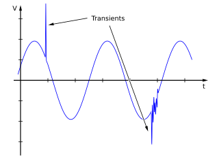
In electrical engineering, spikes are fast, short duration electrical transients in voltage, current, or transferred energy in an electrical circuit.

A substation is a part of an electrical generation, transmission, and distribution system. Substations transform voltage from high to low, or the reverse, or perform any of several other important functions. Between the generating station and consumer, electric power may flow through several substations at different voltage levels. A substation may include transformers to change voltage levels between high transmission voltages and lower distribution voltages, or at the interconnection of two different transmission voltages.
A surge protector is an appliance or device designed to protect electrical devices from voltage spikes.
In electrical engineering, partial discharge (PD) is a localized dielectric breakdown (DB) of a small portion of a solid or fluid electrical insulation (EI) system under high voltage (HV) stress. While a corona discharge (CD) is usually revealed by a relatively steady glow or brush discharge (BD) in air, partial discharges within solid insulation system are not visible.

A residual-current device (RCD), residual-current circuit breaker (RCCB), or ground-fault circuit interrupter (GFCI) is a device that quickly breaks an electrical circuit to prevent serious harm from an ongoing electric shock. Injury may still occur in some cases, for example if a human falls after receiving a shock, or if the person touches both conductors at the same time which an RCD won't prevent.

An arc-fault circuit interrupter (AFCI) also known as an arc-fault detection device (AFDD) is a circuit breaker that breaks the circuit when it detects an electric arc in the circuit it protects to prevent electrical fires. An AFCI selectively distinguishes between a harmless arc, and a potentially dangerous arc.

In electric power distribution, automatic circuit reclosers (ACRs) are a class of switchgear which is designed for use on overhead electricity distribution networks to detect and interrupt momentary faults. Also known as reclosers or autoreclosers, ACRs are essentially high voltage rated circuit breakers with integrated current and voltage sensors and a protection relay, optimized for use as an overhead network distribution protection asset. Commercial ACRs are governed by the ANSI/IEEE C37.60, IEC 62271-111 and IEC 62271-200 standards. The three major classes of operating voltage are 15.5 kV, 27 kV and 38 kV.
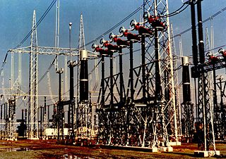
In an electric power system, switchgear is composed of electrical disconnect switches, fuses or circuit breakers used to control, protect and isolate electrical equipment. Switchgear is used both to de-energize equipment to allow work to be done and to clear faults downstream. This type of equipment is directly linked to the reliability of the electricity supply.

An electronic component is any basic discrete device or physical entity in an electronic system used to affect electrons or their associated fields. Electronic components are mostly industrial products, available in a singular form and are not to be confused with electrical elements, which are conceptual abstractions representing idealized electronic components.
Power system protection is a branch of electrical power engineering that deals with the protection of electrical power systems from faults through the disconnection of faulted parts from the rest of the electrical network. The objective of a protection scheme is to keep the power system stable by isolating only the components that are under fault, whilst leaving as much of the network as possible still in operation. Thus, protection schemes must apply a very pragmatic and pessimistic approach to clearing system faults. The devices that are used to protect the power systems from faults are called protection devices.
In the design of electrical power systems, the ANSI standard device numbers identifies the features of a protective device such as a relay or circuit breaker. These types of devices protect electrical systems and components from damage when an unwanted event occurs, such as an electrical fault. Device numbers are used to identify the functions of devices shown on a schematic diagram. Function descriptions are given in the standard.
In an electric power system, a fault or fault current is any abnormal electric current. For example, a short circuit is a fault in which current bypasses the normal load. An open-circuit fault occurs if a circuit is interrupted by some failure. In three-phase systems, a fault may involve one or more phases and ground, or may occur only between phases. In a "ground fault" or "earth fault", current flows into the earth. The prospective short-circuit current of a predictable fault can be calculated for most situations. In power systems, protective devices can detect fault conditions and operate circuit breakers and other devices to limit the loss of service due to a failure.
Islanding is the condition in which a distributed generator (DG) continues to power a location even though electrical grid power is no longer present. Islanding can be dangerous to utility workers, who may not realize that a circuit is still powered, and it may prevent automatic re-connection of devices. Additionally, without strict frequency control the balance between load and generation in the islanded circuit is going to be violated, leading to abnormal frequencies and voltages. For those reasons, distributed generators must detect islanding and immediately disconnect from the circuit; this is referred to as anti-islanding.
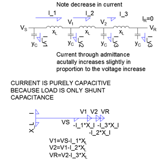
In electrical engineering, the Ferranti effect is the increase in voltage occurring at the receiving end of a very long AC electric power transmission line, relative to the voltage at the sending end, when the load is very small, or no load is connected. It can be stated as a factor, or as a percent increase.
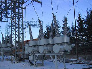
Sulfur hexafluoride circuit breakers protect electrical power stations and distribution systems by interrupting electric currents, when tripped by a protective relay. Instead of oil, air, or a vacuum, a sulfur hexafluoride circuit breaker uses sulfur hexafluoride (SF6) gas to cool and quench the arc on opening a circuit. Advantages over other media include lower operating noise and no emission of hot gases, and relatively low maintenance. Developed in the 1950s and onward, SF6 circuit breakers are widely used in electrical grids at transmission voltages up to 800 kV, as generator circuit breakers, and in distribution systems at voltages up to 35 kV.
Most of the terms listed in Wikipedia glossaries are already defined and explained within Wikipedia itself. However, glossaries like this one are useful for looking up, comparing and reviewing large numbers of terms together. You can help enhance this page by adding new terms or writing definitions for existing ones.
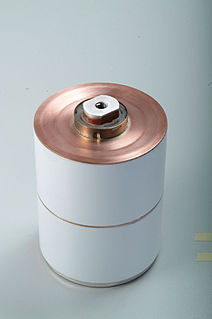
In electrical engineering, a vacuum interrupter is a switch which uses electrical contacts in a vacuum. It is the core component of medium-voltage circuit-breakers, generator circuit-breakers, and high-voltage circuit-breakers. Separation of the electrical contacts results in a metal vapour arc, which is quickly extinguished. Vacuum interrupters are widely used in utility power transmission systems, power generation unit, and power-distribution systems for railways, arc furnace applications, and industrial plants.


