
A ramjet is a form of airbreathing jet engine that requires forward motion of the engine to provide air for combustion. Ramjets work most efficiently at supersonic speeds around Mach 3 and can operate up to Mach 6.

A carburetor is a device used by a gasoline internal combustion engine to control and mix air and fuel entering the engine. The primary method of adding fuel to the intake air is through the Venturi tube in the main metering circuit, though various other components are also used to provide extra fuel or air in specific circumstances.

The turbofan or fanjet is a type of airbreathing jet engine that is widely used in aircraft propulsion. The word "turbofan" is a combination of the preceding generation engine technology of the turbojet, and a reference to the additional fan stage added. It consists of a gas turbine engine which achieves mechanical energy from combustion, and a ducted fan that uses the mechanical energy from the gas turbine to force air rearwards. Thus, whereas all the air taken in by a turbojet passes through the combustion chamber and turbines, in a turbofan some of that air bypasses these components. A turbofan thus can be thought of as a turbojet being used to drive a ducted fan, with both of these contributing to the thrust.
Engine tuning is the adjustment or modification of the internal combustion engine or Engine Control Unit (ECU) to yield optimal performance and increase the engine's power output, economy, or durability. These goals may be mutually exclusive; an engine may be de-tuned with respect to output power in exchange for better economy or longer engine life due to lessened stress on engine components.
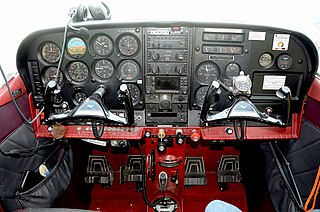
Aircraft engine controls provide a means for the pilot to control and monitor the operation of the aircraft's powerplant. This article describes controls used with a basic internal-combustion engine driving a propeller. Some optional or more advanced configurations are described at the end of the article. Jet turbine engines use different operating principles and have their own sets of controls and sensors.

In automotive engineering, an exhaust manifold collects the exhaust gases from multiple cylinders into one pipe. The word manifold comes from the Old English word manigfeald and refers to the folding together of multiple inputs and outputs.
An inlet manifold or intake manifold is the part of an internal combustion engine that supplies the fuel/air mixture to the cylinders. The word manifold comes from the Old English word manigfeald and refers to the multiplying of one (pipe) into many.

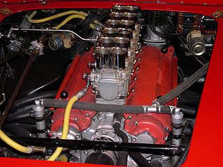
Alfa Romeo Twin Spark (TS) technology was used for the first time in the Alfa Romeo Grand Prix car in 1914. In the early 1960s it was used in their race cars (GTA, TZ) to enable it to achieve a higher power output from its engines. And in the early and middle 1980s, Alfa Romeo incorporated this technology into their road cars to enhance their performance and to comply with stricter emission controls.
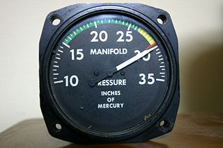
Manifold vacuum, or engine vacuum in an internal combustion engine is the difference in air pressure between the engine's intake manifold and Earth's atmosphere.

A ram-air intake is any intake design which uses the dynamic air pressure created by vehicle motion, or ram pressure, to increase the static air pressure inside of the intake manifold on an internal combustion engine, thus allowing a greater massflow through the engine and hence increasing engine power.

An intake is an opening, structure or system through which a fluid is admitted to a space or machine as a consequence of a pressure differential between the outside and the inside. The pressure difference may be generated on the inside by a mechanism, or on the outside by ram pressure or hydrostatic pressure. Flow rate through the intake depends on pressure difference, fluid properties, and intake geometry.
The manifold absolute pressure sensor is one of the sensors used in an internal combustion engine's electronic control system.

A crankcase ventilation system (CVS) removes unwanted gases from the crankcase of an internal combustion engine. The system usually consists of a tube, a one-way valve and a vacuum source.
A jet engine performs by converting fuel into thrust. How well it performs is an indication of what proportion of its fuel goes to waste. It transfers heat from burning fuel to air passing through the engine. In doing so it produces thrust work when propelling a vehicle but a lot of the fuel is wasted and only appears as heat. Propulsion engineers aim to minimize the degradation of fuel energy into unusable thermal energy. Increased emphasis on performance improvements for commercial airliners came in the 1970s from the rising cost of fuel.
A throttle is a mechanism by which fluid flow is managed by constriction or obstruction.

In supersonic aerodynamics, an unstart refers to a generally violent breakdown of the supersonic airflow. The phenomenon occurs when mass flow rate changes significantly within a duct. Avoiding unstarts is a key objective in the design of the engine air intakes of supersonic aircraft that cruise at speeds in excess of Mach 2.2.
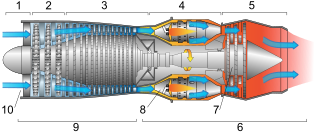
This article briefly describes the components and systems found in jet engines.
An airbreathing jet engine is a jet engine in which the exhaust gas which supplies jet propulsion is atmospheric air, which is taken in, compressed, heated, and expanded back to atmospheric pressure through a propelling nozzle. Compression may be provided by a gas turbine, as in the original turbojet and newer turbofan, or arise solely from the ram pressure of the vehicle's velocity, as with the ramjet and pulsejet.
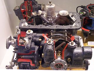
Of the three types of carburetors used on large, high-performance aircraft engines manufactured in the United States during World War II, the Bendix-Stromberg pressure carburetor was the one most commonly found. The other two carburetor types were manufactured by Chandler Groves and Chandler Evans Control Systems (CECO). Both of these types of carburetors had a relatively large number of internal parts, and in the case of the Holley Carburetor, there were complications in its "variable venturi" design.
Airflow, or air flow, is the movement of air. The primary cause of airflow is the existence of air. Air behaves in a fluid manner, meaning particles naturally flow from areas of higher pressure to those where the pressure is lower. Atmospheric air pressure is directly related to altitude, temperature, and composition.


