Related Research Articles
The Unified Modeling Language (UML) is a general-purpose, developmental, modeling language in the field of software engineering that is intended to provide a standard way to visualize the design of a system.

Software architecture refers to the fundamental structures of a software system and the discipline of creating such structures and systems. Each structure comprises software elements, relations among them, and properties of both elements and relations. The architecture of a software system is a metaphor, analogous to the architecture of a building. It functions as a blueprint for the system and the developing project, laying out the tasks necessary to be executed by the design teams.
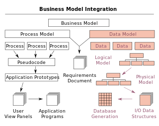
A data model is an abstract model that organizes elements of data and standardizes how they relate to one another and to the properties of real-world entities. For instance, a data model may specify that the data element representing a car be composed of a number of other elements which, in turn, represent the color and size of the car and define its owner.

A system context diagram (SCD) in engineering is a diagram that defines the boundary between the system, or part of a system, and its environment, showing the entities that interact with it. This diagram is a high level view of a system. It is similar to a block diagram.
In software and systems engineering, the phrase use case is a polyseme with two senses:
- A usage scenario for a piece of software; often used in the plural to suggest situations where a piece of software may be useful.
- A potential scenario in which a system receives an external request and responds to it.
A modeling language is any artificial language that can be used to express information or knowledge or systems in a structure that is defined by a consistent set of rules. The rules are used for interpretation of the meaning of components in the structure.

In systems engineering and software engineering, requirements analysis focuses on the tasks that determine the needs or conditions to meet the new or altered product or project, taking account of the possibly conflicting requirements of the various stakeholders, analyzing, documenting, validating and managing software or system requirements.

In systems engineering, information systems and software engineering, the systems development life cycle (SDLC), also referred to as the application development life-cycle, is a process for planning, creating, testing, and deploying an information system. The systems development life cycle concept applies to a range of hardware and software configurations, as a system can be composed of hardware only, software only, or a combination of both. There are usually six stages in this cycle: requirement analysis, design, development and testing, implementation, documentation, and evaluation.
In computing, a scenario is a narrative of foreseeable interactions of user roles and the technical system, which usually includes computer hardware and software.
In software engineering and systems engineering, a functional requirement defines a function of a system or its component, where a function is described as a specification of behavior between inputs and outputs.
Object-oriented analysis and design (OOAD) is a technical approach for analyzing and designing an application, system, or business by applying object-oriented programming, as well as using visual modeling throughout the software development process to guide stakeholder communication and product quality.

Business Process Model and Notation (BPMN) is a graphical representation for specifying business processes in a business process model.
Object-oriented design is the process of planning a system of interacting objects for the purpose of solving a software problem. It is one approach to software design.
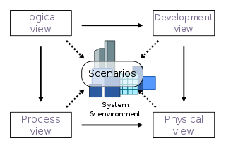
4+1 is a view model used for "describing the architecture of software-intensive systems, based on the use of multiple, concurrent views". The views are used to describe the system from the viewpoint of different stakeholders, such as end-users, developers, system engineers, and project managers. The four views of the model are logical, development, process and physical view. In addition, selected use cases or scenarios are used to illustrate the architecture serving as the 'plus one' view. Hence, the model contains 4+1 views:
In requirements engineering, requirements elicitation is the practice of researching and discovering the requirements of a system from users, customers, and other stakeholders. The practice is also sometimes referred to as "requirement gathering".

Misuse case is a business process modeling tool used in the software development industry. The term Misuse Case or mis-use case is derived from and is the inverse of use case. The term was first used in the 1990s by Guttorm Sindre of the Norwegian University of Science and Technology, and Andreas L. Opdahl of the University of Bergen, Norway. It describes the process of executing a malicious act against a system, while use case can be used to describe any action taken by the system.

A view model or viewpoints framework in systems engineering, software engineering, and enterprise engineering is a framework which defines a coherent set of views to be used in the construction of a system architecture, software architecture, or enterprise architecture. A view is a representation of a whole system from the perspective of a related set of concerns.
A goal model is an element of requirements engineering that may also be used more widely in business analysis. Related elements include stakeholder analysis, context analysis, and scenarios, among other business and technical areas.
Business requirements, also known as stakeholder requirements specifications (StRS), describe the characteristics of a proposed system from the viewpoint of the system's end user like a CONOPS. Products, systems, software, and processes are ways of how to deliver, satisfy, or meet business requirements. Consequently, business requirements are often discussed in the context of developing or procuring software or other systems.
Software architecture description is the set of practices for expressing, communicating and analysing software architectures, and the result of applying such practices through a work product expressing a software architecture.
References
- 1 2 John McDermott and Chris Fox (Dec 1999). "Using Abuse Case Models for Security Requirements Analysis" (PDF). Proceedings of the 15th Annual Computer Security Applications Conference, 1999. (ACSAC '99): 55–64.
- ↑ Chun Wei (Johnny), Sia, Misuse Cases and Abuse Cases in Eliciting Security Requirements, http://www.cs.auckland.ac.nz/compsci725s2c/archive/termpapers/csia.pdf